Chieftain MK3 Build

Forum for discussion relating to the Chietain MBT
Post Reply
User avatar
John Clarke
Posts: 1631
Joined: Sun Oct 17, 2010 10:06 pm
Location: Staffordshire
Been liked: 1729 times

Re: Chieftain MK3 Build

Post by John Clarke »

That's a work of art David.
Can't quite make out the casting lettering :lol:
67707_0.jpg
67707_0.jpg (151.02 KiB) Viewed 7562 times
True about the track links, there are so many versions of the horn, as long as there is one per track link, anything goes.
Oh Man, I only ride em I don't know what makes them work,
Definatley an Anti-Social type

David Battson
Posts: 169
Joined: Mon Jul 23, 2007 9:51 pm
Has liked: 108 times
Been liked: 232 times

Re: Chieftain MK3 Build

Post by David Battson »

Hi John,
Thanks for the comments, but you're a hard task master. Unfortunately I don't have your apparent patience when it comes to the placement of those pesky plastic characters. Whilst it's work in progress at the moment, those particular casting numbers are unlikely to be on the final to do list, so please don't waste too much time trying to find them.
David

User avatar
John Clarke
Posts: 1631
Joined: Sun Oct 17, 2010 10:06 pm
Location: Staffordshire
Been liked: 1729 times

Re: Chieftain MK3 Build

Post by John Clarke »

I shouldn't consider some comments from myself other than tongue in cheek. So far your build is fantastic, more accurate than I think anyone could imagine.
The build is close to my heart, being my favourite model, showing what could have been supplied with more development.
The level so high I cannot imagine how your going to decide to rectify some of the many changes you may want to in the future.
I continue to struggle with the accuracy some of the physical aspects of the model and dislike having to constantly wonder how I make those changes Id like to make. Chopping and changing. Is that the way to go? I dont know. I used to be indecisive, but now, I'm not sure :lol:
It must be said, Armortek's brillantly painted models setting a great standard too.
Setting that all aside I do enjoy putting the casting lettering, eye sight permitting.
Not always perfect and adding some humour where possible if numbers / letters not known.
CND, (campaign for nucular disarmament) can be found on the model, commonly cropping up during the cold war. :oops: there are others.
There's not enough smiles in the world, but your build and others on the forum certainly brings a smile of appreciation to me. :D
Oh Man, I only ride em I don't know what makes them work,
Definatley an Anti-Social type

David Battson
Posts: 169
Joined: Mon Jul 23, 2007 9:51 pm
Has liked: 108 times
Been liked: 232 times

Re: Chieftain MK3 Build

Post by David Battson »

Moving to the rear of the tank, the next area to work on are the final drive units.
When viewed side on the outer edge of the kit final drive, from about the 2 to 7 o’clock position, is roughly flush with the top of track spuds, whereas on the real thing a little more of the track is on show, although exactly how much seems to vary from vehicle to vehicle.


kit final drive side profile
kit final drive side profile .jpg (135.1 KiB) Viewed 7360 times

To improve the look, the radius of the outer edge was reduced to expose more of the track link. ‘Button mushroom’ shape fixings were made up from steel, drilled, tapped to M3 and embedded into the housing sides to replace the kit fixings. The opposite edge from 8 to 10 o’clock was pulled inward and the top edge from 10 to 12 o’clock cut at the correct angle rather than horizontal, which should help reduce any problems of the track rubbing against it.

work in progress
work in progress
A new, repositioned, quill shaft housing and cover was made up. The hex shape in the centre of the quill shaft being ‘formed’ by hammering a hex shaped bar into a suitably undersized hole.
reshaped final drive side
reshaped final drive centre

When viewed from the rear, the kit final drive units appear a little too skinny. To help give that distinctive Chieftain rear end look, the units were given a bit of Botox with the addition of a 5mm thick crescent of aluminium to the inside bolting face and a couple of aluminium disks slipped over the output shaft. Not sure what the two grooves in the final gear housing are for (stress relief in the casting ?), but they’re just about visible on the real thing and don’t know yet how much the sprocket will cover up, so on they go.
David

kit final drive rear
wider final drive rear
A couple of pictures of the real thing to finish. FYI John I have spotted the casting letters on the test bed and the answer is no !
David
test bed
test bed
bench test.jpg (123.47 KiB) Viewed 7360 times
better days.jpg
better days.jpg (71.14 KiB) Viewed 7360 times

Stephen White
Site Admin
Posts: 3108
Joined: Sat Oct 11, 2008 7:05 pm
Location: Dorset
Has liked: 1022 times
Been liked: 2091 times
Contact:

Re: Chieftain MK3 Build

Post by Stephen White »

David, you’ve a masterful eye for detail. Well done for including the quill shaft end cap retaining screw. It was one of the things which had to be checked regularly.

No retaining screw - end cap rotates and falls off - quill shaft moves axially - tank drive on one side fails - tank hits wall or passing civilian. It happened.

Great build, good to follow.

Stephen.

User avatar
John Clarke
Posts: 1631
Joined: Sun Oct 17, 2010 10:06 pm
Location: Staffordshire
Been liked: 1729 times

Re: Chieftain MK3 Build

Post by John Clarke »

Wow, expertly done David, I think I can just make out the casting number FV0MGOTT (My eyesight's poor) though I don't think I'd bother either. :lol:
I seen other builds with the jacking bolt added. Two on the outside one or two on the inside, Usually they've only put forward one on like yours. There's casting letters near to the known inside one. I may add them later. (Jacking bolts that is :roll: )
Stephen, whats the insurance premium on a Chieftain? (Full comp) :shock:
SAM_1543.JPG
Oh Man, I only ride em I don't know what makes them work,
Definatley an Anti-Social type

David Battson
Posts: 169
Joined: Mon Jul 23, 2007 9:51 pm
Has liked: 108 times
Been liked: 232 times

Re: Chieftain MK3 Build

Post by David Battson »

Final drive gear housing inner face profile.

In order to finish off the inner face of the final drive housings, a couple of other details needed to be put in place first.

Work in progress
Work in progress
Starting with the hull rear plate, which was repositioned relative to the re-profiled final drives using measurements taken from the real thing at Bovington (thank you Adrian :D ). The slope angle of the rear plate to the vertical was also reduced from roughly 7 degrees in the kit to the correct 5 degrees. The combination of these two changes meant that the top edge of the rear plate by the engine deck ended up moving forward toward the turret by 16mm.

gear case - rear plate offset
With the rear plate located, the second detail to do were the hull side plates which, although flush with the rear plate on the kit, actually extend out a little to support the final drives. Despite having moved the rear plate forward, an annoyingly thin sliver of extra metal still needed to be grafted on to the outer edge to enable the correct profile to be completed. The exposed edges were also thinned slightly to reflect the scale thickness of the hull side plates on the real thing.
Finally with these adjustments done, the inner face of the gear case could be reprofiled and finished to match the shape of the side plate extension. Jacking bolt and oil drain plug also added.

Finished profiles
Finished profiles
Final drive inner face

Currently I've fitted the Armortek specified cap head screws to hold the gear case halves together, but would really prefer to use the more realistic looking hex heads instead. Has anyone ever had a gear case fail and come apart from using alternative fixings ?

David

User avatar
Richard Goodwin
Posts: 422
Joined: Fri Mar 15, 2019 6:46 pm
Has liked: 292 times
Been liked: 284 times

Re: Chieftain MK3 Build

Post by Richard Goodwin »

Mine didn't David when I test drove her, see Page 14 of my build for layout and fixings used.

David Battson
Posts: 169
Joined: Mon Jul 23, 2007 9:51 pm
Has liked: 108 times
Been liked: 232 times

Re: Chieftain MK3 Build

Post by David Battson »

Hi Richard,
Many thanks for sharing your experience. I've just re-watched the great video you posted, you certainly put your Chieftain through it's paces which should have shown up a weakness if there was one.
Cheers David

User avatar
John Clarke
Posts: 1631
Joined: Sun Oct 17, 2010 10:06 pm
Location: Staffordshire
Been liked: 1729 times

Re: Chieftain MK3 Build

Post by John Clarke »

Totally brilliant build David. :mrgreen:
I'm looking forward to Richard completing the ultimate Youngjae's Armortek model road test.
First, the sit on and ride test, checking the suspension durability.
The extremely high ramp test, checking it's climbing ability.
Finally, the all important cross the potato field patch several times test, checking the models longevity, he even got it home......... eventually
Awesome stuff 8)
Oh Man, I only ride em I don't know what makes them work,
Definatley an Anti-Social type

David Battson
Posts: 169
Joined: Mon Jul 23, 2007 9:51 pm
Has liked: 108 times
Been liked: 232 times

Re: Chieftain MK3 Build

Post by David Battson »

Fitting the hull floor/bottom Plate

With the location of the hull rear plate now determined, the bottom plate could now also be finally positioned and fixed into place.
To start, the bottom edge of the rear plate was trimmed off a little to make space for a new ‘fish tail‘ transition piece. The kit transition detail was hammered back flat with the rest of the bottom plate.
The combined effect of my earlier work to increase the bottom plate ‘v’ angle and raise the hull sides meant that the kit bottom plate was no longer wide enough, leaving a sizable gap between it and the hull side edges. To help line things up, strips of scrap metal were temporarily bolted around the bottom plate perimeter to rest on the hull side plates. This ensured that when the gaps were filled in, the hull side plate edges formed a perfect extension of the bottom plate profile.
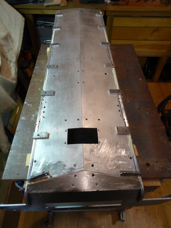
Lining up the bottom plate using temporary fixings
The various drain/access covers were made up and added to complete the look. The large cover was inserted from the inside through a hole in the bottom plate to enable the frame to align with the tip of the bottom plate v along the centreline.
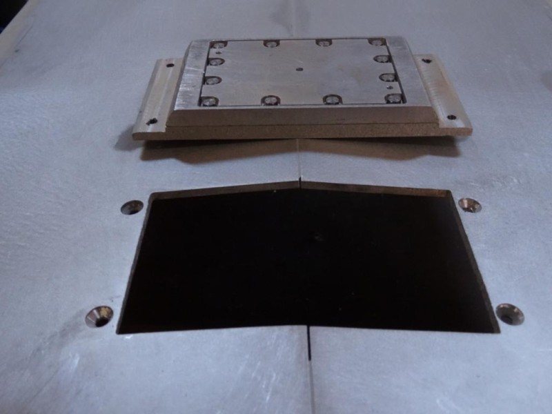
large inspection cover
Large inspection cover 1

Tightening up the hull turned out to be not as straightforward as on previous models, due to the effect of the ‘v’ shaped hull floor. Both hull side plates were slightly bowed, which is fairly normal as stresses are released in the aluminium plate during machining. Ordinarily these bends are easily pulled back straight when the sides are drawn in toward the floor plate as the hull is bolted together and the fixings are tightened up. However with Chieftain, the tendency was for the side plates to stay put and instead the tension to be taken up by ‘stretching’ out the new 10 degree v angle I had created in the bottom plate. The reason for this was no doubt partly self inflicted as I had cut the bottom plate in half along the centre line so it had much less inherent strength compared to the original kit piece. To counter this problem, at each suspension unit location, a strip of aluminium was bolted transversely across the floor inside the tank in order to take the strain and tie the two hull sides together.

From this experience, it is evident that with Chieftain’s relatively long and slender bath tub hull and lack of any bulkheads to tie the two sides together low down across the bottom plate v, great care will be required when jacking the tank off the ground to ensure no lasting damage is inflicted.

David

User avatar
Richard Goodwin
Posts: 422
Joined: Fri Mar 15, 2019 6:46 pm
Has liked: 292 times
Been liked: 284 times

Re: Chieftain MK3 Build

Post by Richard Goodwin »

David,

Even though I didn't cut my floor down the middle, I was still concerned about jacking it so I used a piece of insulated plasterboard which was carved out to the shape of the floor. Like so....
test sit.jpg
test sit.jpg (74.73 KiB) Viewed 6759 times
The plasterboard was then cut to size and reinforce underneath with a sheet of ply once the bogies were fitted. A motorcycle lift is then used to raise the model off the ground. It seems to work at the mo but the tanks nowhere near fully loaded yet!

Keep up the good work :mrgreen:

David Battson
Posts: 169
Joined: Mon Jul 23, 2007 9:51 pm
Has liked: 108 times
Been liked: 232 times

Re: Chieftain MK3 Build

Post by David Battson »

Hi Richard,
That looks like a very good idea, I definitely need to make up some sort of 'V' shaped cradle to spread the load before lifting the hull.
I suspect that if you applied a point load to the middle of the underside of a laden Chieftain kit with something like a small trolley jack, you could easily flatten the v in the bottom plate, which would spread the sides in the middle end realign the central suspension units - not an easy job to repair.
David

David Battson
Posts: 169
Joined: Mon Jul 23, 2007 9:51 pm
Has liked: 108 times
Been liked: 232 times

Re: Chieftain MK3 Build

Post by David Battson »

Front Toe Plate
Moving to the front of the tank, the last part of the lower hull bath tub to complete is the toe plate, which together with the glacis help to create that iconic, and for the time ground breaking, Chieftain look. My old Tamiya Chieftain kit is no good as a reference for the build because it still has the boxed out front that was used to hide the secret design from prying eyes.

Measuring up the toe plate against the real thing, the slope angle of the kit nose is correct at 45 degrees, however the ‘V’ angle is less than it should be and it sits between rather than extending slightly beyond the hull side plates. Instead of trying to improve the look by modifying the kit toe plate, which is a substantial chunk of metal, I took the easier option of covering it with a piece of 3mm aluminium sheet. To make sure the nose V bend occurred in the right place and with a reasonable radius, the inside of the plate was thinned down along the centre line and it was bent over a suitably sized round bar to the required 8 degrees (4 degrees either side of the centreline).

The slope length of the new toe plate nose was also cut to scale and is shorter than the kit piece. In the photos, the scribe indicates the level of the top of the new nose which now finishes further down the slope and hence further inboard compared to the kit piece. In order to correct this problem and avoid shortening the front of the tank the new toe plate was pulled forward so that (in plan view at least) it’s top edge was back in line with the tip of the glacis casting.

top of toe plate nose height
toe plate brought forward
new toe plate
new toe plate
Pulling the new toe plate forward left a gap of 6mm between its outer edges and the start of the hull sides which meant that the idler wheel brackets were now in the wrong position. Rather than trying to move the kit idler mounting brackets forward, rectangles of 6mm aluminium plate were inserted into the gaps to act as new mounting points for the idler wheels. This gives the new toe plate an overall look much closer to that of the real thing, where idler mountings were formed from extensions of the front armour, as shown in the drawing taken from one of Stephen's posts.
new toe plate with idler bracket extensions
toe plate plan
toe plate plan
toe plate plan.jpg (29.15 KiB) Viewed 6615 times

David

User avatar
John Clarke
Posts: 1631
Joined: Sun Oct 17, 2010 10:06 pm
Location: Staffordshire
Been liked: 1729 times

Re: Chieftain MK3 Build

Post by John Clarke »

A Wonderful bit the Chieftain front end is isn't it, I think many of the ones I've seen are down to the artistic licence of the Grinder at Vickers. Not quite a pike, not quite a flat. A sort of curve with an tiny edge in the middle.
Armortek nearly had it but recessed it too much with a top edge square lip missing the smiley shallow V (Or was it V for victory).
Many a slap on Museum quality job redefines the definition. Getting the balance right will take time as I had several goes at it.
I thought at first you were going to use spaced armor on the front end, Noooo, Noooo it's not a cruiser and it could get dented :lol: . Are you, well it looks like your going to pack it out like mine with applique armor. though mine was in one piece
There's nothing like wedge of aluminum that an shouts out an Armortek model.
No pain no gain 8)
front end.jpg
front end.jpg (56.31 KiB) Viewed 6504 times
Oh Man, I only ride em I don't know what makes them work,
Definatley an Anti-Social type

Post Reply