Fitting the hull floor/bottom Plate
With the location of the hull rear plate now determined, the bottom plate could now also be finally positioned and fixed into place.
To start, the bottom edge of the rear plate was trimmed off a little to make space for a new ‘fish tail‘ transition piece. The kit transition detail was hammered back flat with the rest of the bottom plate.
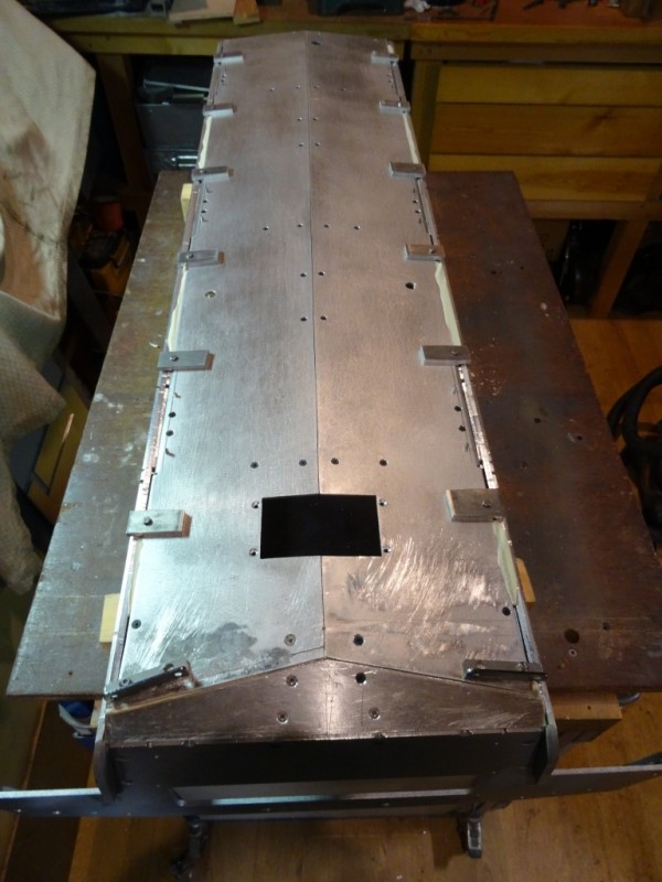
The combined effect of my earlier work to increase the bottom plate ‘v’ angle and raise the hull sides meant that the kit bottom plate was no longer wide enough, leaving a sizable gap between it and the hull side edges. To help line things up, strips of scrap metal were temporarily bolted around the bottom plate perimeter to rest on the hull side plates. This ensured that when the gaps were filled in, the hull side plate edges formed a perfect extension of the bottom plate profile.

- Lining up the bottom plate using temporary fixings
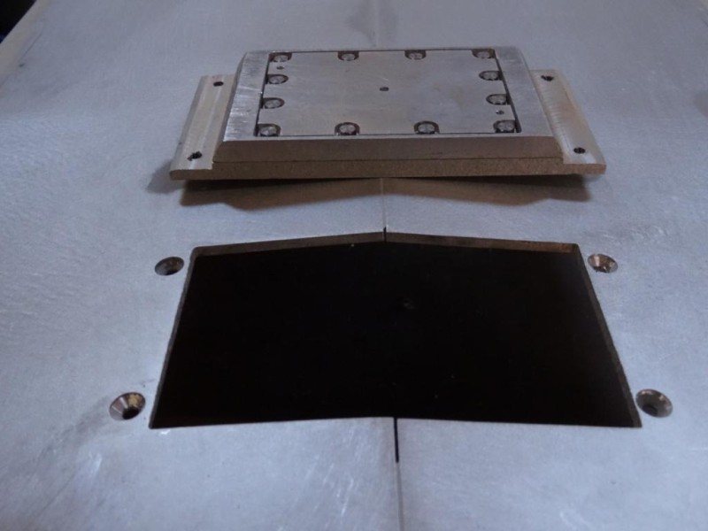
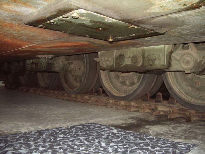
The various drain/access covers were made up and added to complete the look. The large cover was inserted from the inside through a hole in the bottom plate to enable the frame to align with the tip of the bottom plate v along the centreline.

- large inspection cover

- Large inspection cover 1
Tightening up the hull turned out to be not as straightforward as on previous models, due to the effect of the ‘v’ shaped hull floor. Both hull side plates were slightly bowed, which is fairly normal as stresses are released in the aluminium plate during machining. Ordinarily these bends are easily pulled back straight when the sides are drawn in toward the floor plate as the hull is bolted together and the fixings are tightened up. However with Chieftain, the tendency was for the side plates to stay put and instead the tension to be taken up by ‘stretching’ out the new 10 degree v angle I had created in the bottom plate. The reason for this was no doubt partly self inflicted as I had cut the bottom plate in half along the centre line so it had much less inherent strength compared to the original kit piece. To counter this problem, at each suspension unit location, a strip of aluminium was bolted transversely across the floor inside the tank in order to take the strain and tie the two hull sides together.
From this experience, it is evident that with Chieftain’s relatively long and slender bath tub hull and lack of any bulkheads to tie the two sides together low down across the bottom plate v, great care will be required when jacking the tank off the ground to ensure no lasting damage is inflicted.
David