Question for Bob Morey re Panther shackle.

Forum for discussion relating to the Panther
Post Reply
User avatar
Adrian Harris
Posts: 5130
Joined: Thu Jul 12, 2007 10:46 pm
Location: Berkshire (UK)
Has liked: 1484 times
Been liked: 1687 times

Question for Bob Morey re Panther shackle.

Post by Adrian Harris »

Bob, when you created the CNC plot for the Panther shackle, did the CNC machine automatically split to job into two halves or did you have to tell it ?

And if you had to rotate the work to do the second side, how do you achieve the registration of the two halves ?

As you might have guessed, I'm starting to think it mght be fun to buy myself a CNC mill as a Christmas pressie :lol:

Adrian.

User avatar
Robert E Morey
Posts: 2349
Joined: Wed Jul 18, 2007 12:59 am
Location: Seattle, WA USA
Has liked: 161 times
Been liked: 830 times

Post by Robert E Morey »

Hi Adrian,
Well a CNC mill is a great present, but it is pretty involved I've found to get one to make parts. Once mastered though there is no end to what can be made for our models..

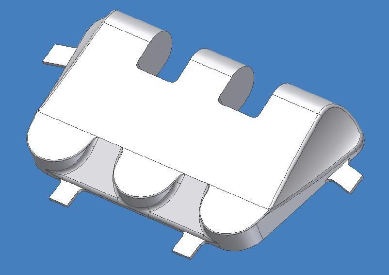
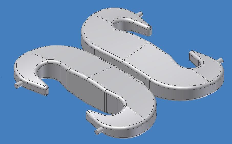
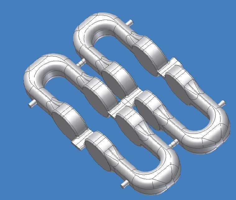
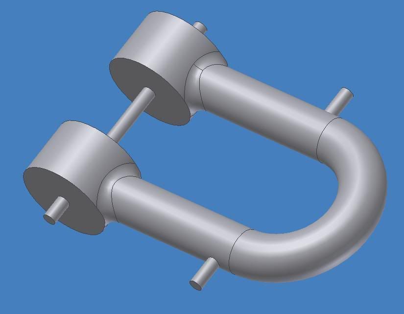
To answer your question on the shackle, the front and back halves are made with the same program. However, this process will only work if the part is symetrical, i.e. the same front and back. The shackles I made are symetrical, and the recovery hook as well - so the same program can be used for the front and back sides. Just run it twice. If the part is different on front to back, then you must have a different program for front and back halves.

Now the registration is another matter. Whenever you create any program you have a defined start point (X,Y, Z coordinate for the program zero pt). You must remember this point when you flip the part over to machine the back side. You must zero the tool from the same edges on the top and bottom side programs - otherwise the part will not come out correct. For example, if your zero point for the top side program is the lower left corner, when you flip the part over to machine the back side, the zero point will be the lower right corner (keeping same zero edge for the tool). Hopefully this makes since? :shock:

CNC is a pretty complicated process, but its not impossible for the average person to learn. One must have a pretty good grasp of manual machine processes and practices before digging into CNC.

The TAIG and Sherline CNC machines are both good investments for the money, and are great machines to learn CNC on. I think the TAIG is a more robust and capable machine than the Sherline, as the TAIG has more steel construction (heavier, more rigid). The Sherline is all Aluminum construction (except for lead screws, bearings, motor, chuck, etc). A good version of either machine can usually be bought on E-bay.

Another piece of the CNC puzzle you must conside is software. There is where the biggest learning curve is. In general there is control software (to control machine tool), CAD software for creating the part model you want to make, and program creating software (convert your CAD model to CNC language). :roll:

Feel free to e-mail me any additional questions you have via the Armortek private message forum or at bobmorey2@yahoo.com.

Good luck and keep us posted on your progress. :wink:
Bob

User avatar
Adrian Harris
Posts: 5130
Joined: Thu Jul 12, 2007 10:46 pm
Location: Berkshire (UK)
Has liked: 1484 times
Been liked: 1687 times

Post by Adrian Harris »

Many thanks for the explanations Bob.

When you say you run the same program for each side, did you create
the whole shackle in CAD or just one half ?

These are the mills I'm currently drooling over:

http://www.cnc-step.com/

If anyone has any bouquets or brickbats I'd love to hear them.

Adrian.

User avatar
Robert E Morey
Posts: 2349
Joined: Wed Jul 18, 2007 12:59 am
Location: Seattle, WA USA
Has liked: 161 times
Been liked: 830 times

Post by Robert E Morey »

Adrian,
Yes I created the whole part in 3D CAD first. But you don't have to, especially for a symetrical part. You could just model half the part I suppose, but I think it would be just as much labor to model half the part as the whole. Its probably better to design the whole part in CAD, this is the Industry standard. One never designs assemblies of half parts - because most good CAD programs allow you to easily section parts (in half) if desired.

The machine you're looking at is considered a CNC router, but is more than capable of doing model parts. The only difference in a CNC router and mill is that routers are somewhat limited in Z height, whereas a mill would have a greater Z travel. But a CNC router typically has more X and Y travel, because it is designed to machine panels of material. Typically these machines route plywood, plastics for signs etc. The model you point out will also machine aluminum quite nicely.

Heres another excellent German made machine. They are quite expensive, but very nice machines. I have a Wabeco D6000E manual lathe and it is the most beautiful machine I own. This is the US source for these machines, but I'm sure there is a UK distributor as well. http://www.mdaprecision.com/

Kind regards,
Bob

User avatar
Robert E Morey
Posts: 2349
Joined: Wed Jul 18, 2007 12:59 am
Location: Seattle, WA USA
Has liked: 161 times
Been liked: 830 times

Post by Robert E Morey »

Adrian,
I posted some more photos in my gallery under CNC to show examples of the symetrical parts: Panther and Tiger shackle, and Recovery hook - which can use the same program front and back side. And also non-symetrical parts: the Panther hatch hinge - which must have a different machining program for the front and back sides. Hopefully you can see how the parts are held in place and machined. As in any project there are many ways to skin the cat.
:twisted: -Bob

User avatar
Adrian Harris
Posts: 5130
Joined: Thu Jul 12, 2007 10:46 pm
Location: Berkshire (UK)
Has liked: 1484 times
Been liked: 1687 times

Post by Adrian Harris »

Thanks for the pictures Bob, it's certainly looking much more likely I'll be getting a CNC machine sometime, though it may have to be a late Christmas present. :evil: :evil:

I've been put onto several companies not so have a whole bunch of specs to browse through. Half the fun really !

With the U bolt, did you make the wax piece as a trial or as a casting master ?

Also, do you have to add the fixing stubs for the pieces or does the CNC system know it has to leave some material ?

Adrian.

User avatar
Robert E Morey
Posts: 2349
Joined: Wed Jul 18, 2007 12:59 am
Location: Seattle, WA USA
Has liked: 161 times
Been liked: 830 times

Post by Robert E Morey »

Adrian,
Great questions. The wax was a prototype project to teach myself the ins and outs when I first got started. It could be used as an investment casting pattern though, in fact my jewelers do exactly that. They machine the pattern in wax and then investment cast the part in precious metal. If you want another of the same pattern - you just machine another one! Pretty cool idea I thought. But when first starting out in CNC and whenever you are unsure a program will run correctly - its a good idea to machine a "soft" material like wax or foam before going to metal. I feel comfortable going straight to metal machining now.

The holding tabs I add to the CAD model. Some CAM (Computer aided machining) programs will help you put the tabs in, but I found they don't always put them where I want them. So I just add them to the CAD model of the part. See photos below of CAD models with holding tabs.
-Bob
Image
Image
Image
Image

User avatar
Adrian Harris
Posts: 5130
Joined: Thu Jul 12, 2007 10:46 pm
Location: Berkshire (UK)
Has liked: 1484 times
Been liked: 1687 times

Post by Adrian Harris »

Great drawings Bob!

I must admit I'm finding it hard to get into the CAD program but I am making slow progress.

With the investment casting, does that require a scaling up of the parts for shrinkage ? Have you had any parts cast this way ? Reason I ask is one of my long distant projects is to get a set full set of T49 track links manufactured,

Having had a play with the CAD program, it looks to be quite a simple task to scale an item up by a certain percentage, which should make building a master quite a simple task.

Re getting a mill, I think I should have the funds by Easter, as long as I can prevent myself getting a second M3!

Adrian.

User avatar
Robert E Morey
Posts: 2349
Joined: Wed Jul 18, 2007 12:59 am
Location: Seattle, WA USA
Has liked: 161 times
Been liked: 830 times

Post by Robert E Morey »

Hello again Adrian,
For CAD I use Solidworks or AutoDesk Inventor. There are some good products from Mecsoft as well (Rhino). Both are reasonably expensive but easy to learn and quite powerful in what they can do. There are many products available so it pays to shop around.

For investment casting you would have to allow for the shrinkage of the material, depending on what material you planned to use. I have not tried this method as it is quite involved equipment wise and only yields one piece. I use a spin cast process which utilizes a rotating rubber mold. This process is much faster and can yield hundreds of pieces of low melt point metal parts (white metal, Pewter or Zinc-Alum). There are several manufacturers of brass detail parts (Steve Winstone for example) that do use the investment cast (or similar) process. It is better for high melting temp metals like brass- which would destroy a rubber mold.

Yes once you have the CAD model of the part done, its easy to scale it or cross section it to whatever size you want. For example you could make the CAD model 1:1 size and scale it to 1/6 or 1/35 scale easily. You could also make the CAD model 1/6 scale and scale it up by 10% to allow for shrinkage of your material (for investment casting).

I hope this information helps you.
Bob

Post Reply