Taper Lock Question

Forum for Armortek Owners to Meet, chat and share knowledge. You are advised to check 'official advice' before carrying out any modifications.
Darryl Vernon
Posts: 52
Joined: Sun Dec 19, 2010 2:53 pm

Taper Lock Question

Post by Darryl Vernon »

I'm about to mount the drive sprockets to my Panther, but the installation instructions from here........:-

http://www.armortek.co.uk/TaperlockLR.jpg

.......do not seem to coincide with the taper lock that I have.

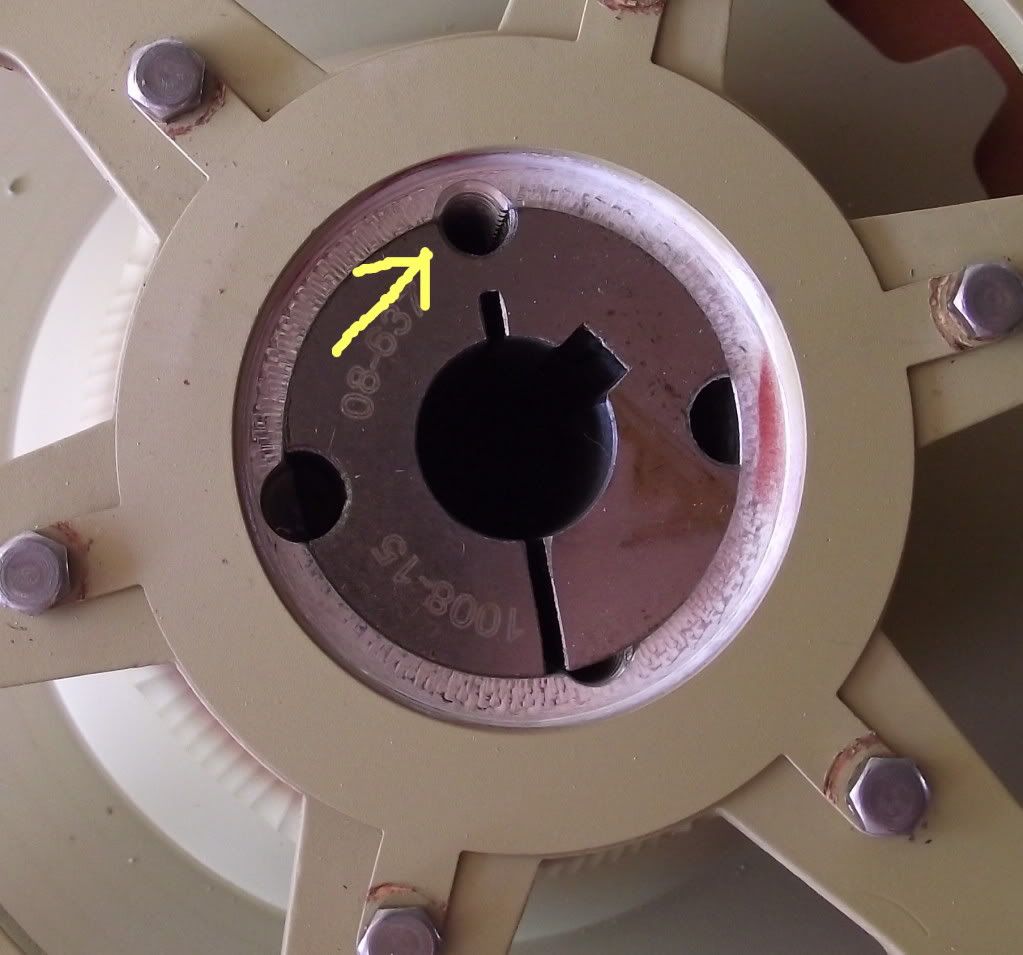
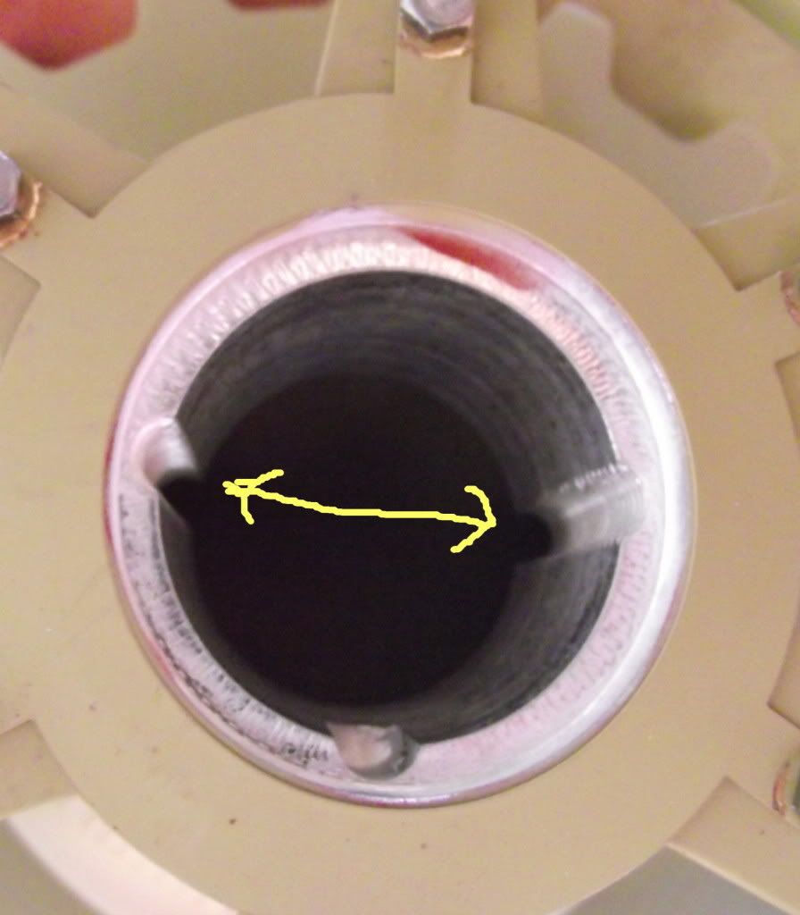
According to those instructions, there are 2 threaded holes in the taper lock, but on mine, there is only one.

Naff looking arrow, shows the only threaded part.
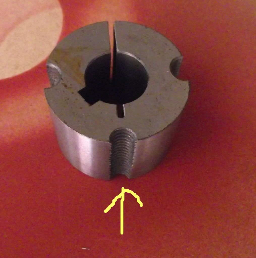
Image

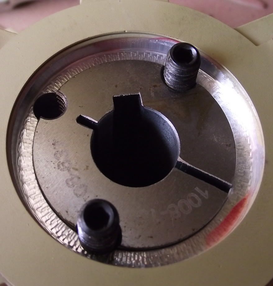
Although my sprockets have two threads.
Image

Threaded hole lined up in sprocket.
Image


Has something been changed, and the instructions not updated, or have I read the instructions wrongly?

Ta muchly.

yves mouton
Posts: 1005
Joined: Fri Nov 06, 2009 7:55 pm
Location: Belgium
Has liked: 1 time
Been liked: 586 times

taperlock

Post by yves mouton »

Hi Darryl,

the one treaded hole in the taperlock is to unscrew the taperlock,
and the 2 treaded holes in the drive sprocket is to secure your taperlock with your 2 bolts.
regards Yves

Darryl Vernon
Posts: 52
Joined: Sun Dec 19, 2010 2:53 pm

Re: taperlock

Post by Darryl Vernon »

yves mouton wrote:Hi Darryl,

the one treaded hole in the taperlock is to unscrew the taperlock,
and the 2 treaded holes in the drive sprocket is to secure your taperlock with your 2 bolts.
regards Yves
Ah! I understand now.
After your explanation, I re-read the instructions, and it now makes complete sense.

Thanks very much Yves. :wink:

Steven Ford
Posts: 154
Joined: Tue Jul 17, 2007 9:41 pm
Location: Northern England
Has liked: 7 times
Been liked: 5 times

Post by Steven Ford »

Word of caution - the narrow neck of metal between the 'unscrew thread' and the middle has a low tolerance to repeated bending. Fit and unfit the taper lock as infrequently and gently as you can.

Darryl Vernon
Posts: 52
Joined: Sun Dec 19, 2010 2:53 pm

Post by Darryl Vernon »

Steven Ford wrote:Word of caution - the narrow neck of metal between the 'unscrew thread' and the middle has a low tolerance to repeated bending. Fit and unfit the taper lock as infrequently and gently as you can.
Point noted. Thanks Steven.

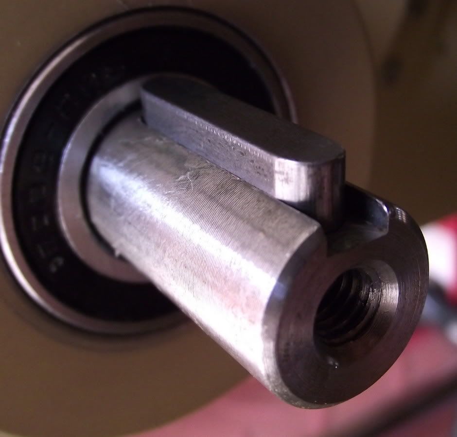
My next problem with this, is........it doesn't fit.

No matter what I do, the key will not go in the slot of the bush.
The tolerance is far too tight.

The key is fully sitting in the slot.
Image

The taper is set up as per instructions.
Image

But the taper will not slide on. The slot will not clear the key to allow it to slide on.

Steven Ford
Posts: 154
Joined: Tue Jul 17, 2007 9:41 pm
Location: Northern England
Has liked: 7 times
Been liked: 5 times

Post by Steven Ford »

I've not done a Panther and I am not an engineer to trade but I imagine that the process is similar.

Your photos seem to show either an oversized key or an undersized slot in the shaft. As you may guess from my previous note I really would caution against taking any more metal off the taper lock and attacking the shaft would require more disassembly than you might wish to contemplate.

Unless anyone feels differently I would suggest reducing the size of the key until a good fit is achieved but do it in small increments.

Just a thought - how many different keys are there in the Panther kit? Is there another that is a better fit?

Darryl Vernon
Posts: 52
Joined: Sun Dec 19, 2010 2:53 pm

Post by Darryl Vernon »

Steven Ford wrote:I've not done a Panther and I am not an engineer to trade but I imagine that the process is similar.

Your photos seem to show either an oversized key or an undersized slot in the shaft. As you may guess from my previous note I really would caution against taking any more metal off the taper lock and attacking the shaft would require more disassembly than you might wish to contemplate.

Unless anyone feels differently I would suggest reducing the size of the key until a good fit is achieved but do it in small increments.

Just a thought - how many different keys are there in the Panther kit? Is there another that is a better fit?
That is my thoughts as well Steven.
Unless anyone can suggest something else, that is the only option.

There are only the two keys.

Thanks for your input Steven. Much appreciated.

phil fitzpatrick
Posts: 2020
Joined: Sat Dec 12, 2009 3:38 pm
Location: Sambourne uk
Been liked: 223 times

Key's and Key Way's

Post by phil fitzpatrick »

Hi Guy's
I had to play with the Key's and Key Way's on my Panzer 111L and Comet,
but I just used emery cloth or wet and dry as Steven said bit by bit,to
where ever needs it,on a flat surface or round a square bit of mettle or
stick for the key way.
Also I found putting the Key in last so you can keep trying it until it
pushes in all the way.
I think the Comet was just a liitl bit off the height of the Key,but the
Panzer was the opposite,so I worked on the key way and key.
Better too big at the start than too small :)
Cheers
Phil

Darryl Vernon
Posts: 52
Joined: Sun Dec 19, 2010 2:53 pm

Re: Key's and Key Way's

Post by Darryl Vernon »

phil fitzpatrick wrote:Hi Guy's
I had to play with the Key's and Key Way's on my Panzer 111L and Comet,
but I just used emery cloth or wet and dry as Steven said bit by bit,to
where ever needs it,on a flat surface or round a square bit of mettle or
stick for the key way.
Also I found putting the Key in last so you can keep trying it until it
pushes in all the way.
I think the Comet was just a liitl bit off the height of the Key,but the
Panzer was the opposite,so I worked on the key way and key.
Better too big at the start than too small :)
Cheers
Phil
Lovely stuff Phil. Thanks for that.

Because this is my first tank build, I'm a bit dubious about doing certain things without first getting advice.

My own thoughts were to use emery to reduce the key slightly, and your input and Stevens, has thus been most helpful.

Cheers! :wink:

phil fitzpatrick
Posts: 2020
Joined: Sat Dec 12, 2009 3:38 pm
Location: Sambourne uk
Been liked: 223 times

Key's

Post by phil fitzpatrick »

Plenty of Elbow Grease and patience and when it goes on just perfect.
you will stand back and say "Wow I did that" :lol:
Cheers
Phil

John Fitzsimons
Posts: 1823
Joined: Tue Dec 14, 2010 3:11 pm
Location: IRELAND,Dublin/Meath
Has liked: 5 times
Been liked: 667 times
Contact:

Post by John Fitzsimons »

Watching this with interest. I'm a dunce at this stuff also. Hope mine fits Ok but if not this will help. Thanks guys

(Just in case anybody read the post before and thought I was drunk I have now corrected the nonsence produced by iphone,)
Last edited by John Fitzsimons on Wed May 11, 2011 11:26 pm, edited 1 time in total.

Paul Fairlamb

Keys & Keyways

Post by Paul Fairlamb »

Gentlemen,
An interesting discussion. I too had similar problems understanding the taper bush installation; largely because I did not read the instructions carefully enough (‘Note to self’).

The Key
Not wishing to teach Grannies to suck eggs, let’s not forget that the function of the key is only to transmit the drive from the drive shaft to the track sprocket. An appropriately sized rusty nail would do. For the initial test runs of my Comet I substituted the supplied steel keys for pieces of wood; the philosophy being that if the tracks jammed the wood would shear; hopefully preventing more serious damage. These little motors may be small but they have a hell of a torque. Unfortunately my wooden keys sheared as I tried to drive the tank from ground up the ramp to the building bench, back to the drawing board – but the philosophy was right.

Fitting Keys
Check for and remove (fine file) any burrs on the edges of the keyways of the shaft and taper bush. Lightly (0.5mm) radius the edges of the key.
Test fit the width of the key into the keyways of the shaft and taper bush with the parts disassembled. If either does not fit, file off the appropriate part of the key. Remember, a key is easy to make; whereas the shaft and bush will cost money if too much is removed.
The fit of the key should be tight as possible up to being tapped in with a light implement (not hammer).
Assemble the bush (correctly installed in the sprocket) onto the shaft. Clamp up until it just turns on the shaft and check the height of the key. If the key is too high, file off the surplus, plus a bit. There is no need to be precise here as the transmission force is taken by the key at the interface of the bush and shaft.
Check the key fits, then partly remove leaving about 5mm in the keyways; fully tighten the bush and remove the key. Check that the sprocket and bush do not wobble on the shaft and whilst not capable of transmitting full motor torque the taper bush should grip the shaft firmly; check also any sprocket locating measurements given in the Armortek instructions.
The key should be reinserted using the light implement. Fully clamping up the taper bush may narrow the keyway slightly, but significantly, it is therefore important that the key fit is checked and if necessary adjusted again. The aim is to prevent the key forcing apart the taper bush and its grip on the shaft.

Point to Note
Our tanks will probably spend as much time going in reverse as forwards, if the key/keyway is laterally/circumferentially sloppy it will eventually allow movement between the bush and shaft which will produce wear, repairs and costs.

Happy tank building,
Paul

Darryl Vernon
Posts: 52
Joined: Sun Dec 19, 2010 2:53 pm

Post by Darryl Vernon »

Paul, thanks very much for your in-depth input.

Very, very helpful.

p.s. My l/h sprocket and track are on, other side should be done tomorrow.

Thanks for the help guys.

Paul Fairlamb

Post by Paul Fairlamb »

Darryl,

I might have been a little late with the comments on the keys and keyways. Anyway I hope the r/h sprocket and track have been installed without problem. Soon be time for a test of some description - good luck.

I'm at the painting stage, rather boring really as I'm not very good at it and hence the finish is not very consistant yet.

Happy tank building

Paul

John Fitzsimons
Posts: 1823
Joined: Tue Dec 14, 2010 3:11 pm
Location: IRELAND,Dublin/Meath
Has liked: 5 times
Been liked: 667 times
Contact:

Post by John Fitzsimons »

Play in Tiger 1 drive shaft.
I have got to the stage where my key fits perfectly after a rub with sandpaper. My problem is that the gear sprocket inside the gear case has about .5mm play. Setting the sprocker wheel on the shaft calls for a 16.5 mm gap between the inner edge of the sprocket wheel and the hull side. At which point do I measure the gap since the shaft is allowing .5mm play. If I measure the gap with the shaft pulled outwards the fastmers rub slightly against the gear case.

I presume the play is normal?

Post Reply