Sound unit
-
Andy Payne
- Posts: 76
- Joined: Sat Sep 15, 2007 12:47 pm
- Location: Cairns AUSTRALIA
- Been liked: 2 times
Sound unit
Hey Guys , I have checked the forum for this problem and ask if anyone has more experience rectifying it.Bench tested my running gear today , all when fairly straight forward but for one point with the sound unit.With the engine sound running normally when I operate the turret traverse the sound unit restarts the engine.There was a previous post regarding this issue and it was identified that wiring capacitors into turret traverse motor would correct the problem.If this is the case could anyone advise me of the type/value of the capacitors to install.Everything else is going well and I'd hoped to move the tiger under her own power this weekend , but on Saturday arvo I discovered some fasteners missing and can't acquire any until Monday ,so I'll have to wait .Anyway thanks for any help in advance with my sound problem.
-
Michael McGaren
- Posts: 14
- Joined: Fri Jul 13, 2007 11:41 am
- Location: United States
Andy,
I had the same problem with my Sherman, this did work to solve the problem (so far so good anyway )
)
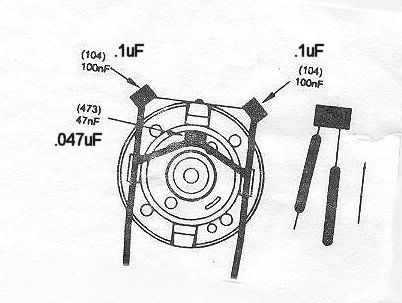
I used 0.1uF metalized film capacitors and a good silver solder. At first I used ceramic disc capacitors and a cheap rosin type solder that I had lying around, and it worked for a while but then stopped after a few days. Also scrape off some of the outer coating of the metal case on the motor so that you get a good connection.
I hope this helps,
Mike
I had the same problem with my Sherman, this did work to solve the problem (so far so good anyway
I used 0.1uF metalized film capacitors and a good silver solder. At first I used ceramic disc capacitors and a cheap rosin type solder that I had lying around, and it worked for a while but then stopped after a few days. Also scrape off some of the outer coating of the metal case on the motor so that you get a good connection.
I hope this helps,
Mike
-
Andy Payne
- Posts: 76
- Joined: Sat Sep 15, 2007 12:47 pm
- Location: Cairns AUSTRALIA
- Been liked: 2 times
-
Michael McGaren
- Posts: 14
- Joined: Fri Jul 13, 2007 11:41 am
- Location: United States
-
Ad Wouterse
- Posts: 292
- Joined: Thu Jul 12, 2007 4:32 pm
- Location: The Netherlands
- Been liked: 2 times
-
Andy Payne
- Posts: 76
- Joined: Sat Sep 15, 2007 12:47 pm
- Location: Cairns AUSTRALIA
- Been liked: 2 times
-
Graham Ord
- Posts: 249
- Joined: Mon Jul 16, 2007 11:15 am
- Location: BRIXHAM
- Has liked: 4 times
- Been liked: 16 times
SOUND AND TURRET ROTATION
Have followed your instructions and now have continuous sound. Thanks for the help I have received off various people.
Graham
-
Roland Mann
- Posts: 174
- Joined: Thu Jul 12, 2007 4:45 pm
- Location: Stavenow, Germany
- Been liked: 19 times
Hi Everyone in charge with an early Tiger,
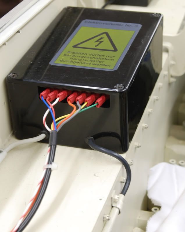
I got to the point to start my sound for the first time ever. However, in my chematic diagramm there are no colours and I wonder if the box is connected correctly. Can someone help me and check and let me know what is right. Any help is very much appteciated. Thank you and best regards
Roland
I got to the point to start my sound for the first time ever. However, in my chematic diagramm there are no colours and I wonder if the box is connected correctly. Can someone help me and check and let me know what is right. Any help is very much appteciated. Thank you and best regards
Roland
Der Weg ist das Ziel.
-
Adrian Harris

- Posts: 5131
- Joined: Thu Jul 12, 2007 10:46 pm
- Location: Berkshire (UK)
- Has liked: 1484 times
- Been liked: 1687 times
Roland.
This is somewhat unscientific but the colours on my Sherman sound unit follow your picture exactly.
The label attached to the top of the unit lists the connetions as:
7 - Blue - 0V
6 - Red - 24V
5 - White/Red - Function (I think this is for the engine start from the RC rcvr)
4 - Orange - Right Track
3 - Grey - Left Track
2 - Yellow - Loudspeaker
1 - Green - Loudspeaker
I've no reason to believe that the sound units from these two models should vary in their connections, though your box does seem to have two additional wires running in through grommets under the main connections
Adrian.
-
Roland Mann
- Posts: 174
- Joined: Thu Jul 12, 2007 4:45 pm
- Location: Stavenow, Germany
- Been liked: 19 times
Hi Adrian,
thank you very much for this check. Yes I believe the Sherman and early Tiger box are the same connections. Probably another Tiger owner will confirm. The numbers are of interest to me. There is another black/withe diagramm giving the numbers without colours. Will double check.
The two cables at the bottom of my box are my own additions. They are for my lights. The black is comming out of my own made main disrtibution box giving 3,3 volt from an extra BEC circuit for the lights, rear and front. The gray one leads to the rearlight. OK, I used Steve's beautiful front head lights but changed the bulbs for a less energy consuming LED in sunny white.
Thanks again for your help - Roland
Der Weg ist das Ziel.
-
Graham Ord
- Posts: 249
- Joined: Mon Jul 16, 2007 11:15 am
- Location: BRIXHAM
- Has liked: 4 times
- Been liked: 16 times
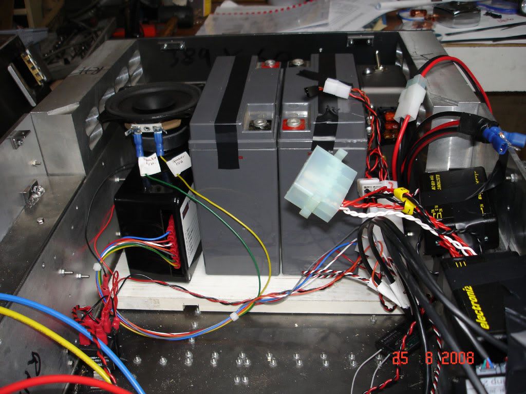
HERES SOME MORE PHOTOS
Hi All
As you can see I soldered my capacitors to a band gripping round the motor on a roughened area to ensure contact.
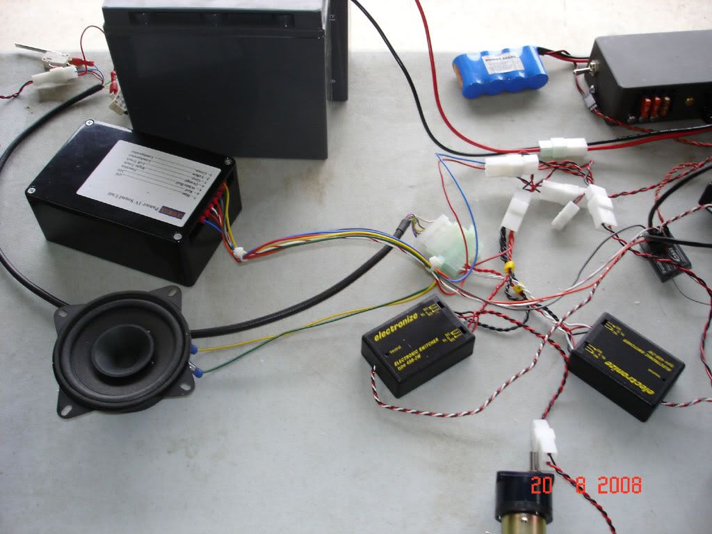
The sound box is shown when temporary assembled by Mark at Armortek on his bench (thank you) and fitted to my P IV later at home.
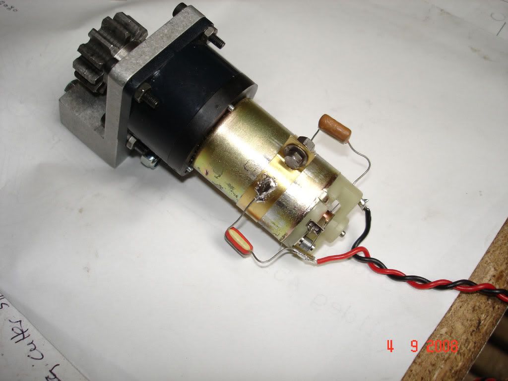
As you can see I soldered my capacitors to a band gripping round the motor on a roughened area to ensure contact.
The sound box is shown when temporary assembled by Mark at Armortek on his bench (thank you) and fitted to my P IV later at home.
Graham
-
Allan Richards
- Posts: 743
- Joined: Thu Jul 12, 2007 10:34 am
- Location: Kent
- Been liked: 10 times