Hi All,
Update 26 Oct 21
Was planning to wait to post until after all rear plate modifications were complete but need to spend more time on the toolbox rack. This is because it will not have a toolbox fitted and so I cannot fix the box to the plate and then fit the rack to the box.

Anyway...
On reflection the 4mm A/F bump stop nuts looked rather small so I drilled and tapped some 5mm A/F hexagonal bar for M3 which hopefully will give a more prototypical result.
Lower Side Plate Mods - Part 2
The actual sponson floor plates are fixed using a scalloped edged right-angled girder. This girder is taper-bolted to the lower plates before being welded in place. I chose to replicate this line of bolts only where it may be seen which is in between the two sets of roof supports. To achieve the look I was after, I simply marked, drilled and tapped the plate so that non-functional fixings could be added with threaded bar (4BA) and a suitable nut (one size smaller 5BA).
The track pin knocker plates are actually welded to the lower side plates. In the kit, they are affixed using countersunk M3 bolts and nuts. I decided to hide the nuts using a similar technique as that for the bump stops. A counter bore (6.0mm by 3.75mm) was milled into the plate and an M3 nut pulled into place. Eventually the nut and exposed bolt thread will be hidden with epoxy putty.
Rear Plate Modifications - Part 1
Please note that the following images may include evidence of changes discussed later and that bolts are often used to protect threads during later machining operations.
Armoured Exhaust Covers: as the attachment bolts are now M5, the corresponding holes were tapped for M5 so that threaded bar could be used to simulate the studs.
Exhaust Attachment: in reality the exhaust pipes are bolted to studs on the rear plate. This will be simulated with M4 threaded bar and nuts, therefore holes were drilled and tapped for M4.
Rear Mudguard Frame: Using dimensions provided by David Byrden (Tiger1.info) I designed a replacement support for the rear mudguards. Redundant holes where tapped and filled using cut down M5 brass bolts in a similar manner to those on the lower side plates.
Jack mountings: I have acquired the excellent 20T jack made by Mark Lawson. After slightly adjusting the position of the mounting brackets to match those shown in reference photographs of 15T jacks I tried out the jack. Obviously the fit will not be perfect as the brackets were relocated when the 20T jack replaced the 15T but it ties-in with the hastily re-equipped look I am going for.
Revised Top Attachment Brackets: As the radiator fan grills are moveable, I decided that the rear corner attachment brackets need modification to make the securing bolts less obvious. The solution was simply to reverse the direction of the bolts and countersink the brackets. Larger counterbores were machined into the rear plate to accommodate the nut. These will eventually be hidden with body filler.
Starter Plate Cover: The external detail of the armoured starter plate aperture cover plate is represented in the kit. The internal detail is, however missing, as the basic kit has the smoke unit located at the rear of the engine bay. I plan to have a fully detailed engine in this model and so I decided that some representation of this plate was required. So to start a suitable ‘cut’ was milled into the rear plate using a boring head.
Fan Drive Mounting (HL210): The fan drive gearbox for the HL 210 was mounted to the rear plate whereas it was mounted to the engine block for the HL 230. If the tank was re-engined it was typical for the mounting bosses to be left in situ. I will feature these on F01 and so the rear plate required holes milling on the inner face.
Manual Starter Plate Mounting Bosses: I had modified the rear plate to allow for a proto-typical arrangement right at the start of the build. It is now time to consider how to fabricate the bosses. The actual system involves a captive nut that rotates a bar in/out of a slot within the boss so that the plate can be demounted. The nut and bar will be represented by an M3 nut and threaded bar that will screw into a M3 tapped hole located within a M5 threaded bar that is screwed and bonded into a tapped hole in the plate. The boss will be fabricated from a 3D printed inserted within some thin walled brass tubing.
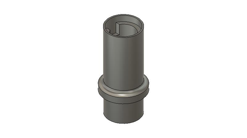
- starter plate posts - external.jpg (13.26 KiB) Viewed 5700 times
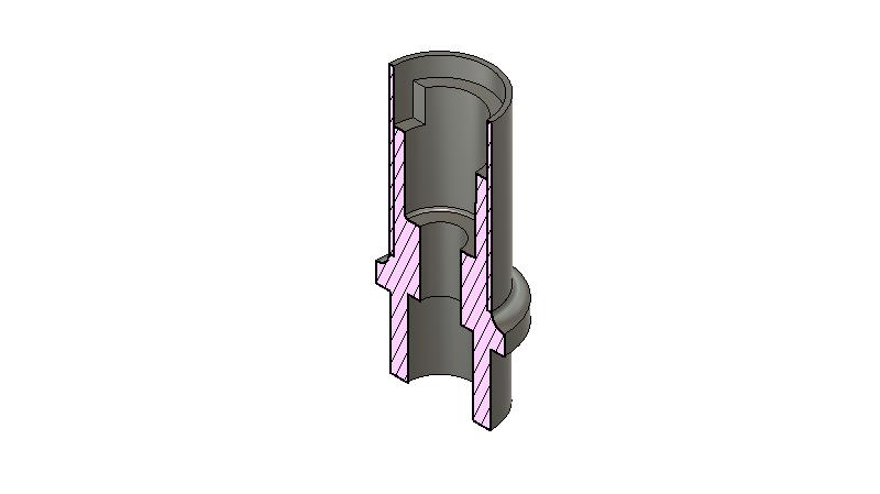
- starter plate posts v2.jpg (17.08 KiB) Viewed 5700 times
More modifications to follow...

Alastair
