Page 13 of 20
Re: Churchill Mk3 number 67
Posted: Fri Feb 09, 2024 1:35 pm
by Gary Richardson
Hi all
I apologise for jumping about on this build but I keep getting over enthusiastic about detailing and forgetting I need to get the lower hull completed and install the motors and modules etc. With that in mind I have put the periscopes to one side while I concentrate on getting the air filter boxes completed and installed.
The M3 16mm and 40mm cap head bolts only engage about 3/4 of the nut threads so I have ordered some 18mm and 50mm bolts, the 50's will be cut to 42mm. For a build out of the box this isn't that crucial and Loctite would ensure they stay in place but I have noticed there is a bracket held in place by the rear bottom 16mm bolt. On my photos it is a cable bracket with a safety strip to ensure the cable stays in place. Hence the longer bolts as it is another part I will add to my AVRE.
In the instruction manual it mentions the three button heads that might foul the air filter unit, mine definitely did so I milled three channels on the rear of the unit for the button heads to sit in.
Next step is to make the covers for the top of the units. I will use 0.6mm brass and hold it in place with M2 threaded rod and nuts. More to follow.
Regards
Gary
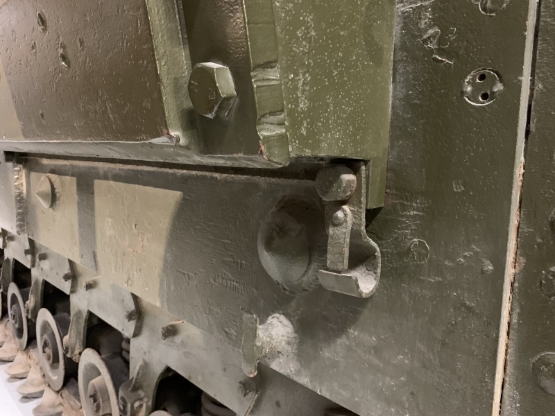
- Note the cable bracket.
Re: Churchill Mk3 number 67
Posted: Fri Feb 09, 2024 5:09 pm
by Gary Richardson
Good evening
I have made the two cable brackets that go at the bottom rear end of the air filter block. I used brass strip and M1.6 nuts for the securing tabs. I also checked my photos and books again which show the air filter blocks are attached with the bolt heads are on the outside, not the nuts. This makes it a lot easier as no cutting down of bolts required as the nuts will be inside the hull.
I am going to the Model Show at the Bovington tomorrow so hopefully I will be able to get some brass strip to do the covers.
Regards
Gary
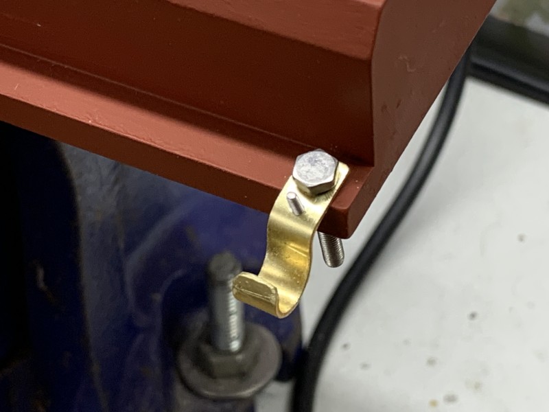
- It took a while to get the correct shape.
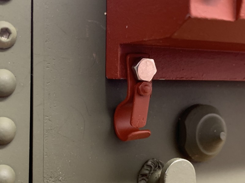
- A nice cable bracket that actually works.
Re: Churchill Mk3 number 67
Posted: Wed Feb 14, 2024 8:41 pm
by Gary Richardson
Hi all
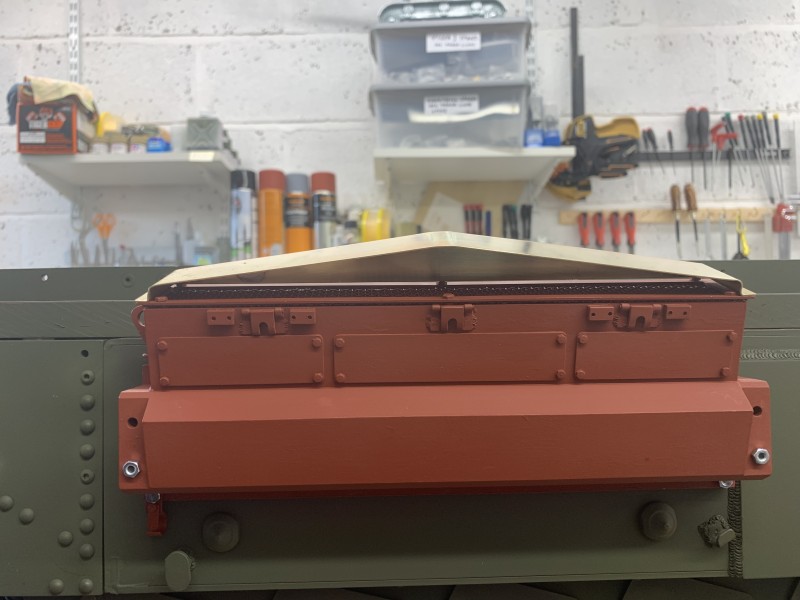
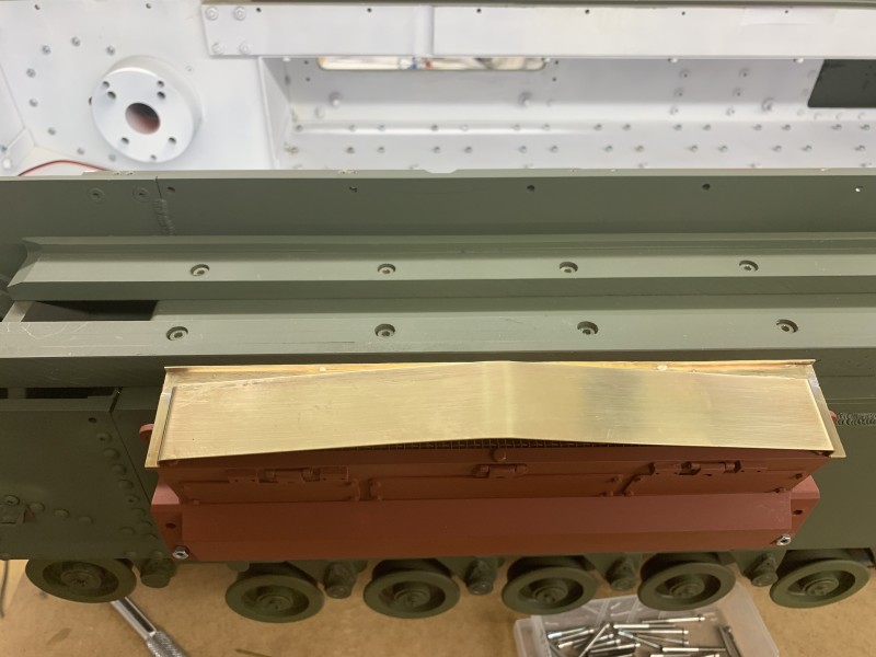
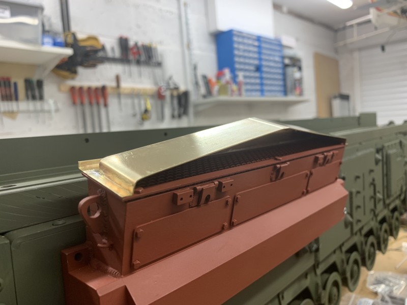
Todays job was to start making the air filter covers. I picked up some suitable brass strips at the model show so began to shape the top part of the cover. This took a bit of trial and error but eventually I got the shape right. I then cut a smaller brass strip to fill the back of the cover and give it some rigidity before adding the rear shaped section. Lead free Silver solder was used to join all the parts and add strength. It still needs tidying up and a thin tube adding along the front top edge. A touch of car body filler and Milliput will ensure it looks ok before priming.
Regards
Gary
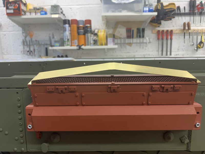
- Top cover bent to shape.

- Rear infill added.
- Gap at bottom of infill is for the rear strip to be soldered in place.
- Rear strip and flange added.
- Almost finished the first cover.
Re: Churchill Mk3 number 67
Posted: Sat Feb 17, 2024 4:13 pm
by Gary Richardson
Good afternoon
I have competed the cover for the air filter block. This has taken quite a bit of time mainly aligning all the parts that had to be silver soldered in place.
The second one is 80% complete and has gone much smoother with just the brass tube to add and the drilling of the bolt holes.
There was a variety of cover styles to choose from and I chose the best features from several. One point was to leave a small flat section on top as this makes clamping it all in place prior to soldering a lot easier. The Armortek frame for the mesh is a bit too short to have the nut and bolt fixing as per full size so I did a field mod and drilled holes through the cover and frame that were half the thread width into the main body. I used M2 threaded studs Araldited in position then added Milliput welds.
Regards
Gary
Re: Churchill Mk3 number 67
Posted: Mon Feb 19, 2024 10:16 pm
by Gary Richardson
Hi all
Well, that's the air filter blocks and covers completed. They have had the top coat of SCC15 sprayed on and are hanging up while the paint dries and hardens. I will install them in a couple of days as I am puppy sitting a Guide dog tomorrow.
Regards
Gary
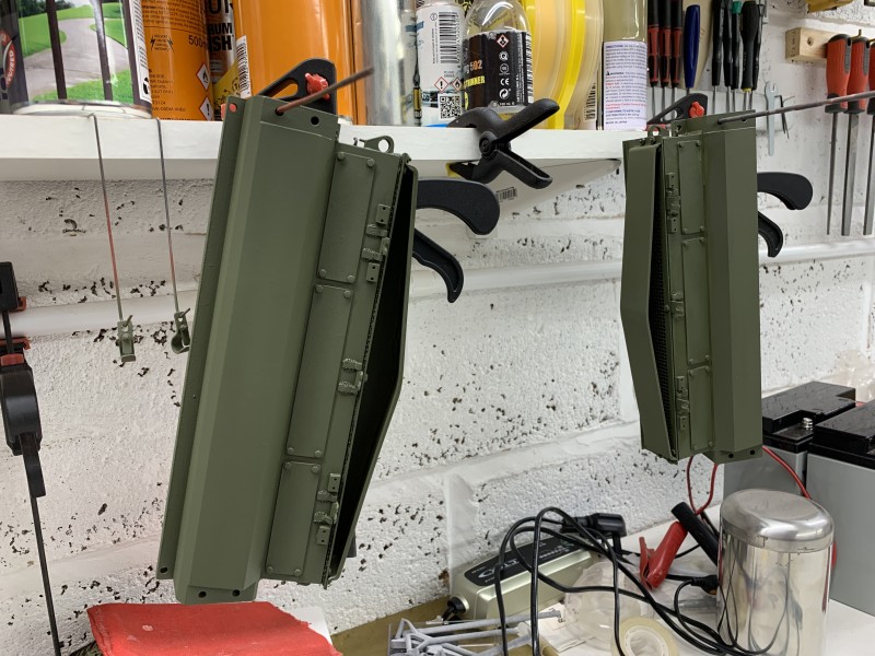
- Top coat of SCC15 has been applied.
Re: Churchill Mk3 number 67
Posted: Wed Feb 21, 2024 3:23 pm
by Gary Richardson
Good afternoon
I have completed the fitting of the air intakes and covers and am pleased to say the rear cover flange just about cleared the lower mudguard. This was lucky as I forgot to measure it beforehand

I still have a few small parts and details to add to the lower hull such as the front cable holder which I will turn on the lathe. Next step is to test the motors and packs and set the transmitter up. I must admit I have inadvertently altered the settings I had for the Tiger and still haven't been able to get it corrected so it doesn't turn properly. I must get this sorted before I do the Churchill settings.
I went to the South West model show and had a chat with Dave, Mark and Tim at the Armorpax stand and Dave showed me the Petard Mortar he has completed for a customer. It was very impressive and has got me thinking how I will go about doing my mortar. More on that topic later

Regards
Gary
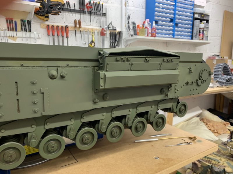
- Air intake discolouration due to paint still being wet
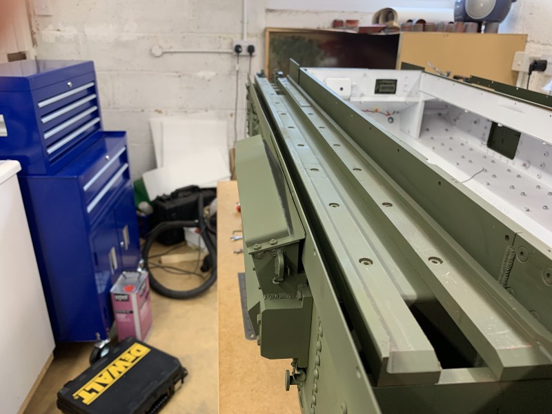
- Air intake cover was a very snug fit
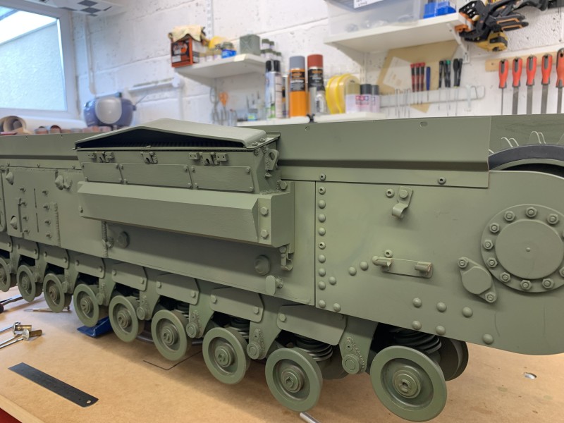
- Air intake
Re: Churchill Mk3 number 67
Posted: Tue Mar 05, 2024 4:06 pm
by Gary Richardson
Hi all
Having just returned from a trip to the Tank Museum to do some more research on the Mk3 AVRE I realised I had made a mistake with the air filter covers. The lip at the back of the cover is level with the rear of the main body and there is an overhang at the front. This also explains why it was so close to the lower mudguard. On the full size the filter wire is lower in the air intake and the metal edges that form the top of the air filter body extend at the front and sides. The front lip actually stops the hinged forks from going past 90 degrees when the wading gear is fitted.
I decided the easiest thing to do was redrill the holes in the cover and use car filler to seal the old ones. Luckily it didn't take lone and now looks more realistic.
Regards
Gary
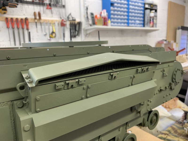
- Cover extends to the front as per full size
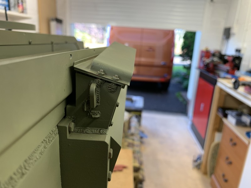
- There is now the correct gap at the back
Re: Churchill Mk3 number 67
Posted: Thu Mar 07, 2024 9:22 am
by Gary Richardson
Good morning
Time to crack on with the front deck, namely the periscopes. I decided to countersink the four base holes and use 2.5mm countersunk screws, the tops are then filled with car filler and smoothed off. This gives a more realistic look and was a quick win.
I will use Milliput to add the welds rounds the sides. The top has been left off for now while I complete the periscope lenses and decide what top I want to add. For those with a 3d printer the tops can have a lot of detail added included a hinged sprung cover.
Regards
Gary
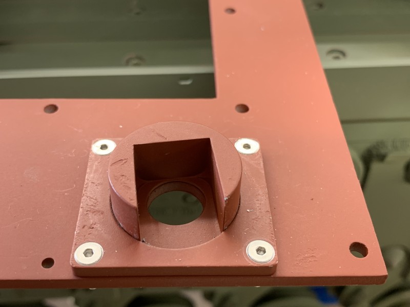
- Holes countersunk for the M2.5 screws.
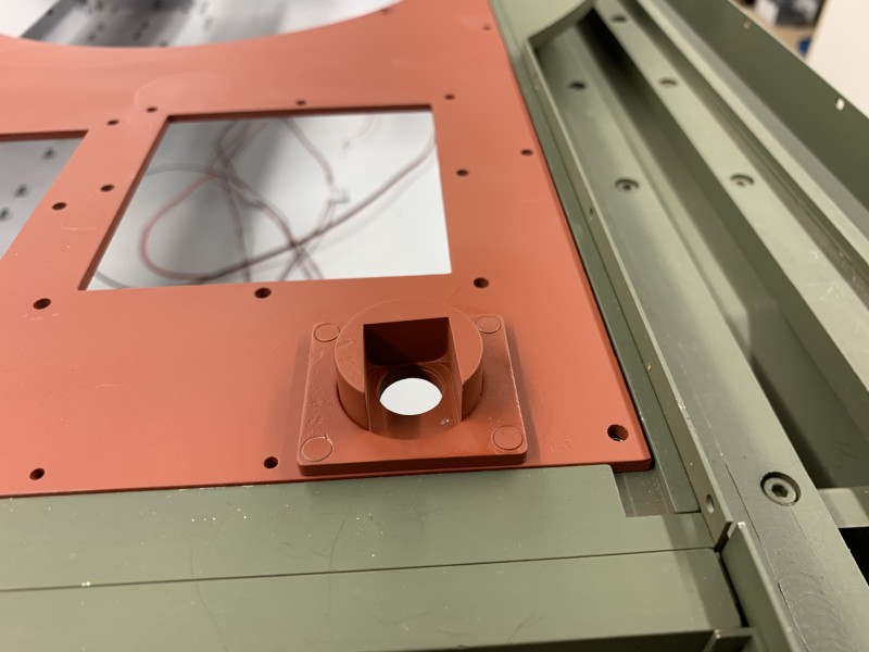
- Allen key hole filled and sanded.
Re: Churchill Mk3 number 67
Posted: Thu Mar 07, 2024 4:40 pm
by Gary Richardson
Hi all
I have added some detail to the driver and loaders hatches. The rivets are 1/16" (1.55mm) aluminium dome heads and the handle is attached using 2.5mm countersunk screws so I can get a flat finish as per full size.
I wanted to check the track fit using 74 links, it took a bit of effort but does connect together bearing in mind the suspension isn't compressed. One thing that did surprise me was how close the track is the the inner hull. This is despite making sure all the bogies were tightened up with them as far outboard as possible then aligning the sprockets.
On the plus side it will make it easier to add the mudguards as there is a lot more clearance on the outer track edge.
The close proximity to the hull means I am favouring a dirty track configuration probably leaving out the centre mudguard section. I think there is a high chance of grass, twigs and dirt jamming between the track and the hull otherwise and I cannot see an easy way to remove debris without removing the tracks/mudguards.
How are the other Churchill builders who are running their tanks finding them when running on grass ? PM me please rather than put it on the build as this is not a moan but rather genuine interest to determine how I continue the build and what path I take.
Regards
Gary
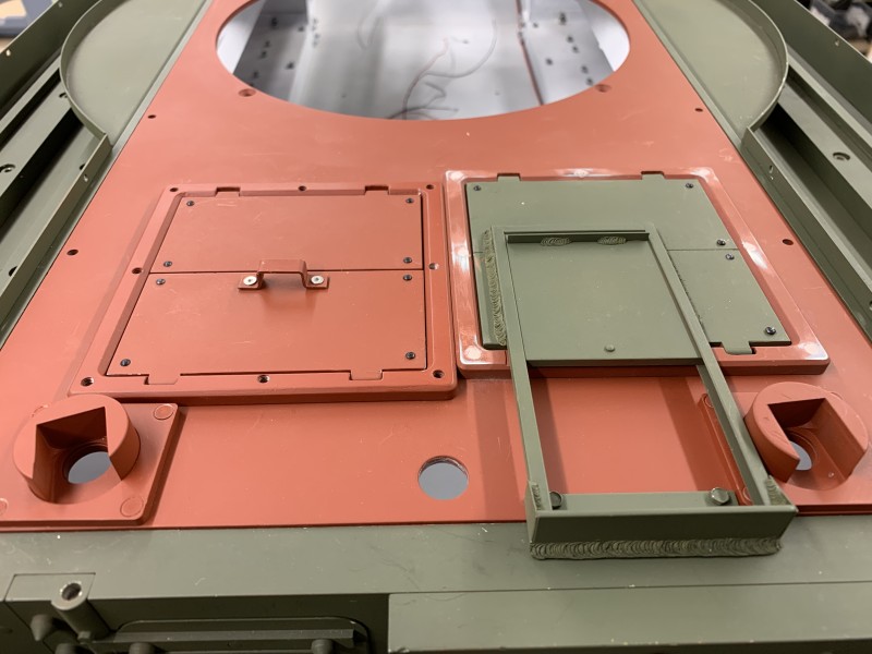
- Adding the detailing.
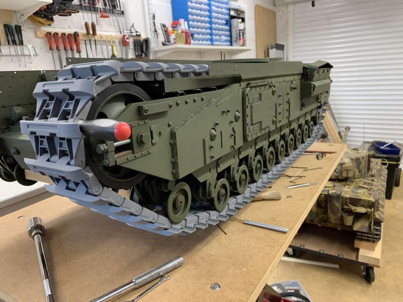
- 74 links without suspension compression.
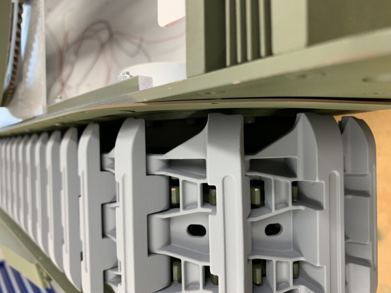
- The track is close to inner hull
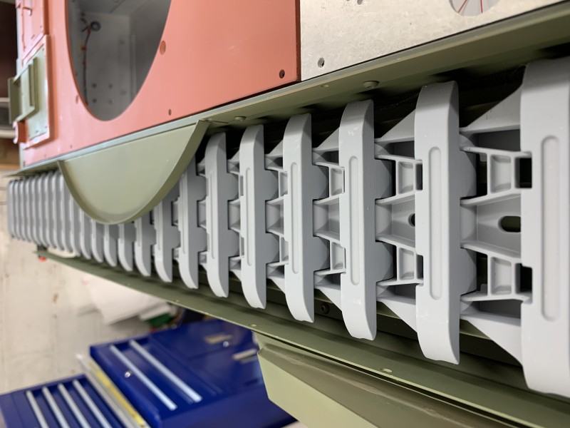
- Mudguard side has room to add some nut fixings
Re: Churchill Mk3 number 67
Posted: Thu Mar 07, 2024 8:53 pm
by Phil Woollard
Some nice work Gary.
Re: Churchill Mk3 number 67
Posted: Mon Mar 11, 2024 1:55 pm
by Gary Richardson
Good afternoon
I have been looking at ways to add more deck detail and wanted to replicate the circular indents and slightly raised marks that exist on the full size.
After a bit of trial and error I settled on using a 5mm nail punch that I modified using the lathe. I turned the domed end until it had a very thin wall and created a narrow round indent when tapped with the hammer. Once I have cleaned the area and given it a coat of red oxide it should look ok.
When I started checking all my photos I realised there are quite a few of these marks scattered about the tank. I will endeavour to recreate enough for it to add the right amount of realism without undoing some of the mods I have already added.
The photo is of the Mk4, courtesy of The Tank Museum.
Regards
Gary
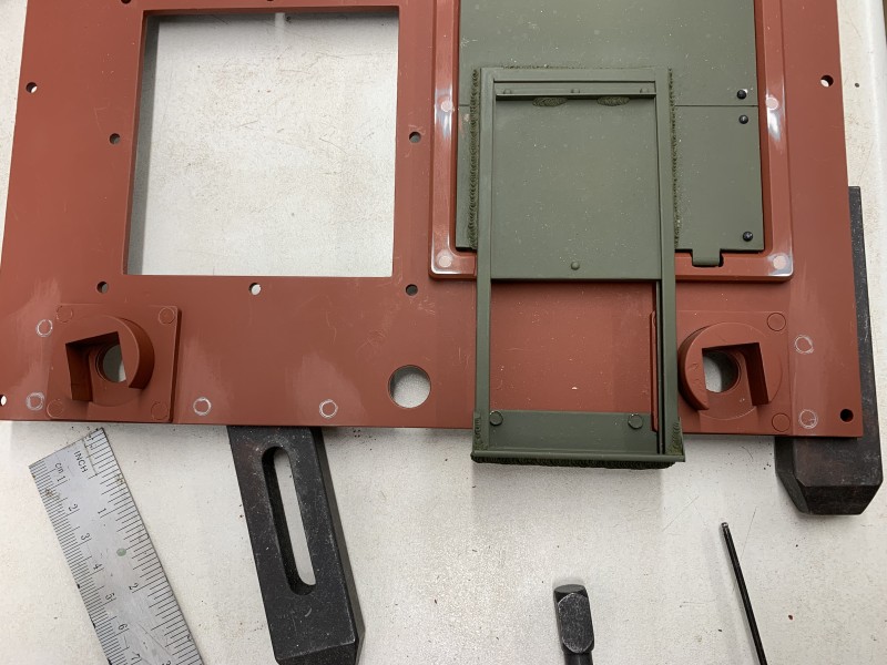
- Adding the circular marks
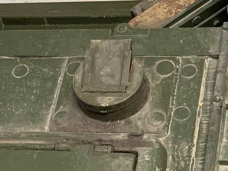
- This photo is the Mk 4 but same as Mk3
Re: Churchill Mk3 number 67
Posted: Mon Mar 11, 2024 7:50 pm
by Adrian Harris
I've seen people reproduce something similar with slotless countersunk bolts from EKP.
But that would require holes drilled and countersunk to the correct depth.
Adrian.
Re: Churchill Mk3 number 67
Posted: Tue Mar 12, 2024 8:56 am
by Gary Richardson
Adrian Harris wrote: ↑Mon Mar 11, 2024 7:50 pm
I've seen people reproduce something similar with slotless countersunk bolts from EKP.
But that would require holes drilled and countersunk to the correct depth.
Adrian.
Hi Adrian
I did think about going down that route but realised it would be difficult to do on the front armour plates due to the closeness of the pannier horns. Using the punch will enable me to get the two ' holes' nearest the horns done. I did a test on a piece of scrap aluminium, on both sprayed and unsprayed sections and it looks ok. Even more so once the paint effects have been added.
To anyone else building a Churchill and wanting to add these sort of effects, whatever method you choose, I would recommend doing them prior to assembly and painting.

I honestly didn't think about this sort of detail when I started the build. It's just the result of numerous trips to the Tank Museum and looking at hundreds of photos

Regards
Gary
Re: Churchill Mk3 number 67
Posted: Wed Mar 13, 2024 5:44 pm
by Gary Richardson
Hi all
Well, I went for it. I used the punch to detail the top of the front armour plate. There are thirteen circles on the full size so that's what I added to mine. I had to redress the punch on the lathe half way through as it stated to deform. Once I have added the oil paint layers and dirt I think they will blend in nicely. On the full size there is a narrow weld just in front of the circles running the entire width of the lower front plate which seems odd as I thought this plate would have been one solid piece of plate. I will check some of the photos I have from other Mk 3's to see if this was generic of has just been done on the one at the Tank Museum. If it is required It will be a very thin Milliput weld so I will have to ensure it will stay in place, maybe cutting a very thin channel in the plate using my Dremel would help give the required adhesion.
Regards
Gary
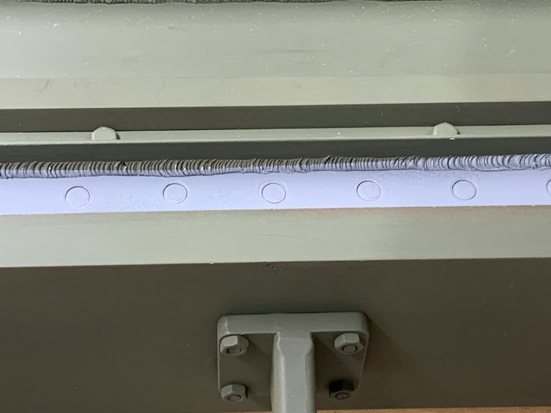
- 5mm punched circles etch primed
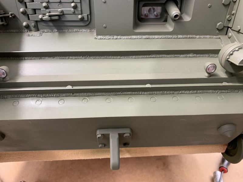
- Top coat applied but still wet.
Re: Churchill Mk3 number 67
Posted: Wed Mar 20, 2024 7:53 am
by Gary Richardson
Good morning all
Over the last few days I needed to make some progress on the turret and declutter the work bench to make space for the motors and power modules etc. As you know I am adding applique armour to my AVRE and that includes the turret front and sides. The turret sides attach using bolts from the outside so I wanted the applique armour to be removable and fixed from inside in case the turret ever needs to be disassembled.
I started by milling the two side plates to the correct size and shape. Next step was to bevel the lower edges and do the cut out on the right hand plate. I marked out where the fixing holes and hand rails needed to be then drilled and tapped the fixing holes for M3 X 16mm bolts which will be tightened from inside the turret keeping it all nice and neat. To ensure both plates lined up they were clamped in place on the milling table before using a 2.5mm cobalt drill through both plates The thread end holes will be filled with car filler prior to priming.
I have order various diameter brass rods for the hand rails and will make a few to see what looks most realistic before drilling the fixing holes and epoxying them in place. Milliput will be used for the welds.
I noticed there are no ninety degree brackets between the front and side plates, just a bottom bracket, so the turret roof holds the front section in the correct vertical position. I want to be able to easily remove the roof without removing bolts and I will probably go down the same route I used for the Tiger 1 which uses magnets and just one bolt. Therefore I will add two small brackets at the front to add rigidity and avoid the Milliput welds cracking.
The next week will be split between testing the electronics and doing the maintenance overhaul on the Tiger so its ready for the open day in April. I may even have the AVRE moving by then and will bring that as well.
Regards
Gary
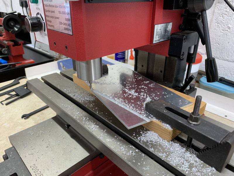
- I love my mill.....
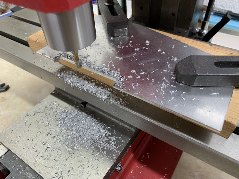
- Shaping the applique armour
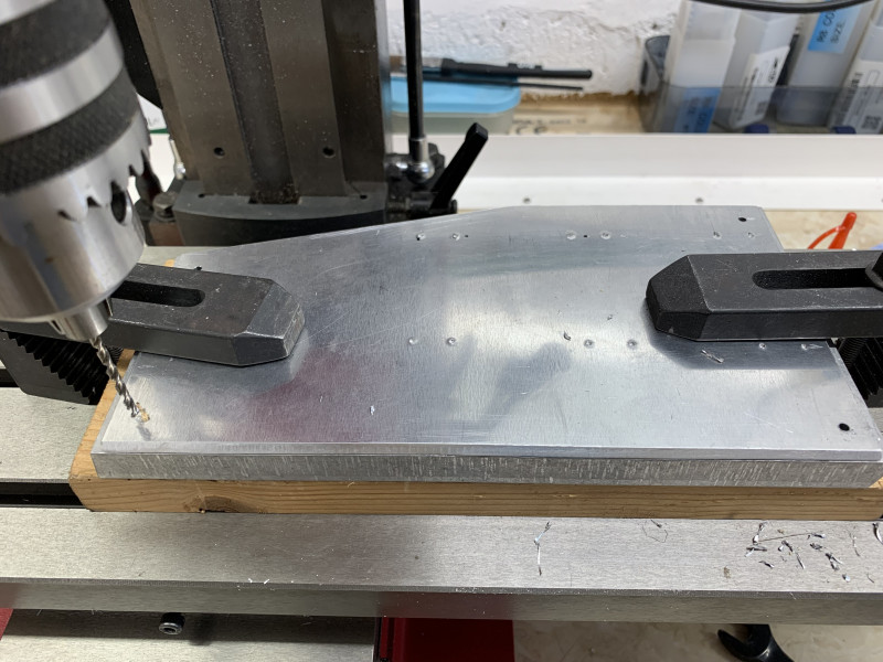
- Using a cobalt drill for the fixing holes.
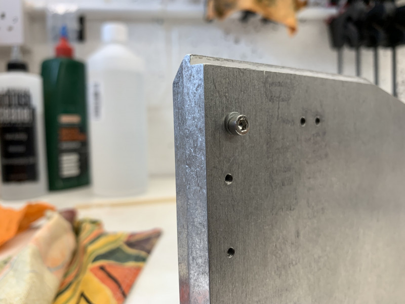
- M3 x 16 bolt with spring washer tightened from inside the turret.
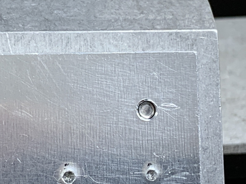
- External hole to be filled prior to priming.
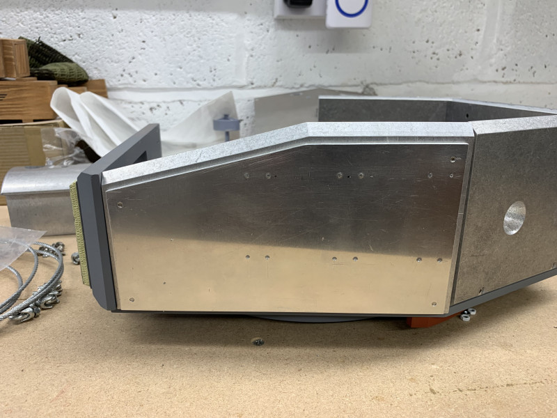
- Left side applique armour, hand grips still to be added.