Hi Chris.
I have uploaded a couple of photos to my gallery of a local M32 Sherman which show the radius arm ends.
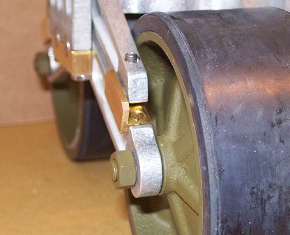
DSCF0001 shows the demarcation line between the radius arm and what I beleive is a sacrificial slide pad which is secured by the bolt.
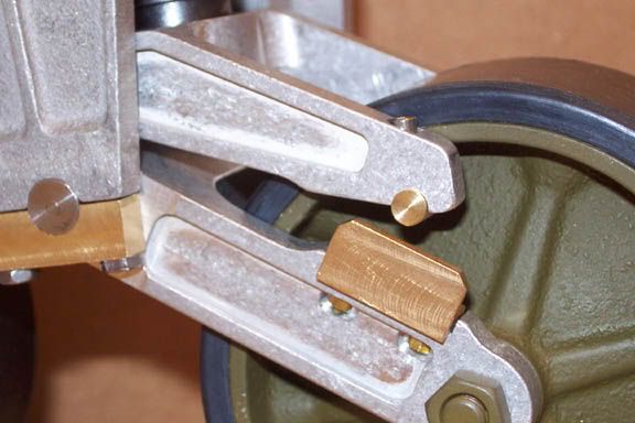
DSCF0042 shows the way the lower slide pad sits within the recess of the radius arm.
Hope these help.
Adrian.
Radius arms
-
Adrian Harris

- Posts: 5132
- Joined: Thu Jul 12, 2007 10:46 pm
- Location: Berkshire (UK)
- Has liked: 1485 times
- Been liked: 1695 times
hello adrian,
many thanks for the pictures, you can see that the slide pad is recessed so that it is flat with the top of the radius arm, so this is what i will do, the picture showing the end of the suspension arm with the bolt in, so does the nut slide on the slide pad and not the suspension arm, and is this a 2mm bolt!,
many thanks for your time, chris.
-
Robert E Morey

- Posts: 2351
- Joined: Wed Jul 18, 2007 12:59 am
- Location: Seattle, WA USA
- Has liked: 161 times
- Been liked: 831 times
Chris,
Not exactly sure which bolt or screw you are referring to. But hopefully the following photos and discussion will answer your question. In the top photo you can see one of the slide pad holding screws which are flat head, so that the bearing in the top arm can slide smoothly over the slide pad and screw heads.
The bottom photo shows the brass bearing which rides on the slide pad. The bearing is also designed so that it keeps the upper arm centered over the lower arm. The bolt in the end of the top arm holds the bearing piece on.
In the real tanks this bolt in the end of the upper arm was a hex or square head, but it did essentially the same thing as the SHCS I used. It pushed on a wear plate that rode on the slide pad. My design is not 100% authentic for practicality and functionality reasons, but it follows the original design in concept.
The slide pad is recessed into the arm for two reasons. I felt the slide pad need to be some reasonable thickness to be robust and strong - so it is thicker than the original. Some other folks have used sheet or thinner matl to make the slide pad, which while more authentic, is way more suseptable to damage from dirt, debris and mechanical malfunction. So to compensate for the increased thickness of the slide pad the arm is recessed, which also provides a nice holding mechanism for the pad. Second it is recessed so the bearing in the upper arm has a smooth field (or lane of travel) over the pad, and doesn't drop off a square ledge at the ends of the pad. You will find when running the tank over rough terrain that the end of the upper arm will travel the entire length of the lower arm - therefore you don't want any raised ledges where the upper arm can hang up or jamb. The round shape of the bearing helps prevent any possible jaming action as well. Hopefully this makes some since?
I suppose for simplicity sake the bearing in the upper arm could be dispensed with all together, but I wasn't real keen on Alum to brass rubbing contact. So I designed the brass upper bearing to ride on the slide pad.
There are .pdf's in the old gallery under my name for all the modification parts and assemblies.
Let me know if you have any other questions - Bob
hello robert,
many thanks for the reply and pictures, all makes sence now, will procede with mods on the arms, the only thing that wories me on the bearing theme is now all the weight is on a small surface area instead of the whole lenght of the suspension arms, time will tell.
thanks again, chris. keep up with the good work.
-
Dale jordan
- Posts: 1456
- Joined: Fri Jul 13, 2007 1:10 am
- Location: Port Macquarie Australia
- Been liked: 514 times
- Contact:
Hello Chris . One thing I found was that the radius arms are a very tight fit into the main housing , I filed the inside of the housing on both sides and polish the area with wet and dry sand paper . That way your raduis arms will move smoothly up and down . If not they will bind and grab when moving up and down . I also made a slot in the ends of my axles to make it easyer to remove the axles . The real sherman had these . Dale.
-
Robert E Morey
- Posts: 2351
- Joined: Wed Jul 18, 2007 12:59 am
- Location: Seattle, WA USA
- Has liked: 161 times
- Been liked: 831 times
-
Robert E Morey
- Posts: 2351
- Joined: Wed Jul 18, 2007 12:59 am
- Location: Seattle, WA USA
- Has liked: 161 times
- Been liked: 831 times
Chris,
I think whatever design you choose, will be essentially be more or less a point contact where the upper arm meets the lower arm. It is more a matter of improving the bearing surfaces. Alum to Alum is a very poor bearing surface especially when dirt and grit is involved - severe galling of the two arms can result.
The brass bearings I designed for the upper arm are approx .25" wide (6mm). There are four of these bearings so the load is actually distributed more evenly on the slide pads throughout the range of motion than the stock setup design without the slide pad. The round bearing surface maintains a constant line of contact with the slide pad at all times.
Hope that all that engineering-ese isn't too confusing .
.
Bob
I think whatever design you choose, will be essentially be more or less a point contact where the upper arm meets the lower arm. It is more a matter of improving the bearing surfaces. Alum to Alum is a very poor bearing surface especially when dirt and grit is involved - severe galling of the two arms can result.
The brass bearings I designed for the upper arm are approx .25" wide (6mm). There are four of these bearings so the load is actually distributed more evenly on the slide pads throughout the range of motion than the stock setup design without the slide pad. The round bearing surface maintains a constant line of contact with the slide pad at all times.
Hope that all that engineering-ese isn't too confusing
Bob
-
colin fairweather
- Posts: 253
- Joined: Fri Aug 17, 2007 4:34 pm
- Location: athlone rep of ireland
- Been liked: 9 times
-
David Brady
- Posts: 710
- Joined: Fri Aug 29, 2008 5:04 pm
- Location: Seaford East Sussex
- Has liked: 215 times
- Been liked: 840 times
-
Adrian Harris
- Posts: 5132
- Joined: Thu Jul 12, 2007 10:46 pm
- Location: Berkshire (UK)
- Has liked: 1485 times
- Been liked: 1695 times
-
David Brady
- Posts: 710
- Joined: Fri Aug 29, 2008 5:04 pm
- Location: Seaford East Sussex
- Has liked: 215 times
- Been liked: 840 times
-
Allan Richards
- Posts: 743
- Joined: Thu Jul 12, 2007 10:34 am
- Location: Kent
- Been liked: 10 times
-
Adrian Harris
- Posts: 5132
- Joined: Thu Jul 12, 2007 10:46 pm
- Location: Berkshire (UK)
- Has liked: 1485 times
- Been liked: 1695 times
David,
I use Macclesfield Model Engineers Supplies:
http://www.maccmodels.co.uk/brassangle.htm
The bolts I used are from the BA range but I can't remember exactly which size I used - I think it was probably 10BA. I do recall at the time I was worried about weakening the arms by drilling through them but actually the worst part was drilling the holes. I tried on some scrap aluminium first and kept breaking the drill bits. I found that it was best to do it in lots of short "pecks" rather than trying to drill it in one go.
Adrian.
-
David Brady
- Posts: 710
- Joined: Fri Aug 29, 2008 5:04 pm
- Location: Seaford East Sussex
- Has liked: 215 times
- Been liked: 840 times