wiring problem

Forum for discussion relating to the Sdkfz 222
Yves Maurice
Posts: 96
Joined: Thu Nov 01, 2007 12:50 am
Location: Near Lyon; France

Post by Yves Maurice »

Hello Lee!..
I have the 6ex RC futaba 2.4 ghz... I hope this will help you to give me some details..Yes I 'm a little afraid by electronic and prefere asking some questions rather than brake all the stuff!!... :?
Yves

leesellars
Posts: 934
Joined: Thu Jul 12, 2007 11:19 am
Location: Nottingham
Has liked: 2 times
Been liked: 15 times

Post by leesellars »

Hello Yves

Right Then here we go
Top RC lead on sound goes to Channel 2
Middle RC lead on sound goes to channel 3
Bottom rc lead on sound goes to Channel 4 right stick left and right.
To program switch Transmitter on then power up. You will the hear 3 klicks press the program button. It will then go through all the sounds it will the klick very fast power off. It is now programed.
To select sound 1 Move the stick 1 to the left and 1 to the right. to select sound 2 move the stick 2 times from the center to the left and 1 to the right to engage and so on.
The program button is on the top right of the sound card. Cut arround the button with a knife to free it up.Sometimes it is schrunk arround with the button on.

Lee
http://www.Facebook.com/newthorpemodels
Dont hit me so early in the morning with those negative waves.
Listen carefully i shall say this only once.
If its not broke dont fix it.
Ich Hatt Einen Kameraden

Yves Maurice
Posts: 96
Joined: Thu Nov 01, 2007 12:50 am
Location: Near Lyon; France

Post by Yves Maurice »

I 'm really wondering about the receiver connections ( numbers of the both channels to be connected) and the DMR because benedini say "alway connect with orange cable at the top " on the sound unit and DMR have blue , red, green leads!...
Please help!!.....
Yves

leesellars
Posts: 934
Joined: Thu Jul 12, 2007 11:19 am
Location: Nottingham
Has liked: 2 times
Been liked: 15 times

Post by leesellars »

Hello Yves

I have given you the reciever connections. On the DMR the Signal wire is the Blue one and that isthe orange connection. If you look at the bottom of the sound card you will see the orange cable uppermost on the bottom of the set of Pins. The DMR goes on the top set of pins with the Blue uppermost.

Lee
http://www.Facebook.com/newthorpemodels
Dont hit me so early in the morning with those negative waves.
Listen carefully i shall say this only once.
If its not broke dont fix it.
Ich Hatt Einen Kameraden

Yves Maurice
Posts: 96
Joined: Thu Nov 01, 2007 12:50 am
Location: Near Lyon; France

Post by Yves Maurice »

Lee are you here? I 'm nor sure about the channels...Because I have on the channel 3 the switch unit....Let me know...A nd what about the DMR?!...
Let me know...
Yves

leesellars
Posts: 934
Joined: Thu Jul 12, 2007 11:19 am
Location: Nottingham
Has liked: 2 times
Been liked: 15 times

Post by leesellars »

Hello Yves

Right then.
You should have Channel 1 and 2 (right stick) For movement
Channel 3 Left stick up and down for turret rotation.
Channel 4 left stick Left and right for sound which is the bottom of the 3 RC leads on the sound card.
The Top rc lead goes to channel 1 reciever
middle rc lead goes to channel 2 reciever
DMR goes to the sound card on the top set nearest the rc leads with the blue uppermost like the rc lead at the bottom of that set of 7 pins.

Lee
http://www.Facebook.com/newthorpemodels
Dont hit me so early in the morning with those negative waves.
Listen carefully i shall say this only once.
If its not broke dont fix it.
Ich Hatt Einen Kameraden

Yves Maurice
Posts: 96
Joined: Thu Nov 01, 2007 12:50 am
Location: Near Lyon; France

Post by Yves Maurice »

Lee, I have now ...
on the receiver:
channel 1: steering servo
channel 2: 1st lead from the sound unit
channel 3: switch unit
channel4: second lead from the sound unit
channel 5: simple servo
And on the sound unit: leads to the fuse box then leads to the speaker and on the 7 pins , I have on the 1st pin ,the DMR with blue wire at the top and the last pin, a 3 wires comming from the bottom card and who was already plug on ....
Is I 'm right? (Not sure!...) :?
Yves

leesellars
Posts: 934
Joined: Thu Jul 12, 2007 11:19 am
Location: Nottingham
Has liked: 2 times
Been liked: 15 times

Post by leesellars »

Hello Yves

This is the connections on the reciever
Channel 1 steering servo
Channel 2 Sound lead top rc
Channel 3 Turret Turn switch unit
Channel 4 Sound lead bottom rc
Channel 5 Turret elevation servo

The Middle rc lead on the sound card is not used. The DMC goes onto the top set of the 7 sets of pins.

Lee
http://www.Facebook.com/newthorpemodels
Dont hit me so early in the morning with those negative waves.
Listen carefully i shall say this only once.
If its not broke dont fix it.
Ich Hatt Einen Kameraden

Yves Maurice
Posts: 96
Joined: Thu Nov 01, 2007 12:50 am
Location: Near Lyon; France

Post by Yves Maurice »

Hello Lee

Thank you for your help. Everything is working now. :D I just have to understand now how I can program all the sounds with MG led ...
Yves

Yves Maurice
Posts: 96
Joined: Thu Nov 01, 2007 12:50 am
Location: Near Lyon; France

Post by Yves Maurice »

Hello everybody!..
Now I' m on the smoke..And this time , it do not works...I' ve made all the wiring as specified on the manuel but the fan is not working at all!..If erveryone have an idea, let me know....Well all is working except the fan; I 'm just listening some little kliks inside the electricals connected to the fan ....
:roll: Yves

leesellars
Posts: 934
Joined: Thu Jul 12, 2007 11:19 am
Location: Nottingham
Has liked: 2 times
Been liked: 15 times

Post by leesellars »

Hello Yves

For the smoke if it is wired up correctly the fan will work only when the throttle is on full ie giveing 24vdc. the fan doesnt work with partial throttle.Also it is polar sensitive ie Red + black -.

lee
http://www.Facebook.com/newthorpemodels
Dont hit me so early in the morning with those negative waves.
Listen carefully i shall say this only once.
If its not broke dont fix it.
Ich Hatt Einen Kameraden

Yves Maurice
Posts: 96
Joined: Thu Nov 01, 2007 12:50 am
Location: Near Lyon; France

Post by Yves Maurice »

Hello Lee
All is working now. :lol: :lol: :lol: :D Thanks.
Yves

Yves Maurice
Posts: 96
Joined: Thu Nov 01, 2007 12:50 am
Location: Near Lyon; France

Post by Yves Maurice »

Hello every body!...
I want to connect A 3V led and the MGsound on my 222 and need help...I ve read the past very interesting comments posted by Ad on the subject but I 'm not sure to understand all he wants to tell...
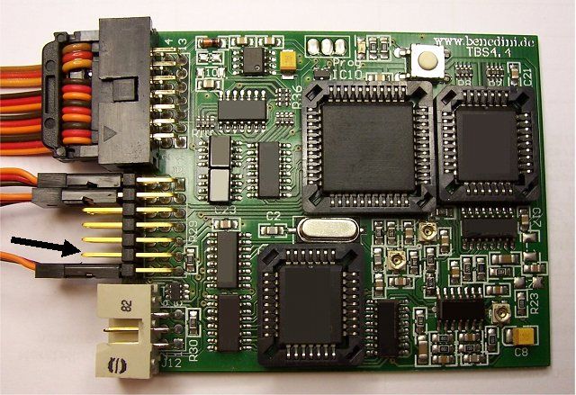
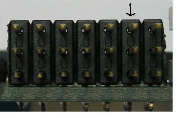
As I have a futaba 6 ex, 2,4 GHZ RC, I want to use the free 6th channel on the receiver and the button connected from it to the right side top on the RC...Is it possible? I think I have to connect the LED on 6th onboard of the sound module output as Benedini said on his flyer but how I can proceed for the sound? A lead from the 6 th channel but to what input or output?
What I must do with the programing button?...
And if all that is not possible, can you let me know what I can do?
Ad if you are here....Or someone who did that!....
Thank you in anticipation!...
Yves :shock:

Ad Wouterse
Posts: 292
Joined: Thu Jul 12, 2007 4:32 pm
Location: The Netherlands
Been liked: 2 times

Post by Ad Wouterse »

Hello Yves,

Connecting a LED to the soundunit is very easy. You do not need any extra switches because the LEDs are controlled by the soundunit. The switch or joystick that you use to play the sounds will also controll the LEDs. You can connect in total 2 normal LEDs directly to the universal onboard outputs.

Image

Image
From the Benedini manual:

6. Universal onboard outputs
Top Output1, Middle +5V Soundunit, Bottom Output2
Both outputs are switching to ground and have integrated 270Ohm resistors. Common LEDs can be connected directly


So you connect the plus wire of 1 (or 2)LEDs to the centre pin and the minus wire to the top pin (and a possible second minus wire to the bottom pin). The easiest way to do this is by using a female servo lead, the loose plug and cable normally connected to a servo. Available in any modelling shop or here http://www.conrad.fr/cordons_servos_3_f ... 458_124565#

The next step is to activate the onboard ouputs.

From the Benedini manual:
Activating the onboard outputs
1. Hold programming button down during power up -> Led flashes twice.
2. Release button
3. Push programming button 2x (select parameter #2)
4. Wait until LED flashes 2x (confirmation of selected parameter #2)
5. Push programming button 2x (set parameter value to 2)
6. Wait until LED flashes 2x. (Confirmation of entered parameter value)
7. LED starts slow continuous double flashing indicating the parameter has been set successfully.
8. Turn off the sound unit
9. Restart the sound unit


When you now select and play the sound of the MG (or the FLAK if you have installed a second LED) the LED in the MG will start and stop flashing simultaneously with the sound.
Please note that this will only work with the first and second "special sound", so the MG and the main gun (or FLAK with the SdKfz 222).

Good luck :D
Cheers,
Ad

Yves Maurice
Posts: 96
Joined: Thu Nov 01, 2007 12:50 am
Location: Near Lyon; France

Post by Yves Maurice »

Hello Ad!..
Thanks for your answer ...But in one hour of test nothing is working.... :cry: frankly I do not know what I must do now!...
I have a 3 V LED connected as you said ( good pictures!) red lead on the middle and the brown on the botom but nothing... ( no 3rd lead because the LED have only 2 leads..) I have trying to connect the brown one at the top but nothing else in more....
On the sound unit, when I push the programming button, the LED flash only 3 or 4 times but not 2 times ( how I can have the 2 times flash?) and after only 3 or 4 times during the parameter time....
Well , I hope you can help me for this problem as I 'm really lost...
ps: how I can have the MG sound on the radio? I have of course the motor but is this the same stick?..
Yves :?

Post Reply