Page 8 of 20
Re: Churchill Mk3 number 67
Posted: Fri Jun 30, 2023 7:49 am
by Gary Richardson
Hi all
I have started doing the additional detailing to the front top plate and the area around the drivers hatch and machine gun. I decided to use brass angle as the thickness was just right but it could equally be made from aluminium. The lower sections have been drilled to take 3.2mm rivets (1/8") which will be glued in place and the back edge milled flat afterwards. The section will be held in place with two countersunk screws for ease of maintenance should I have to take the panniers off. A little filler will hide the countersunk screws.
The two vertical sections will use M2 and 10BA bolts. The M2 bolts will be going into holes that I will tap in the glacis plate while the 10BA bolts will go through the inner guards. I have trimmed the tab off part EX0302 (right side) that bolts to the inner guard as it was getting in the way of the angle iron.
The inner guard will be held in place by the angled brass section. As per the full size the angled section have gaps where they meet that also leaves voids between the glacis plate and the panniers. I will use some filler mixed with micro balloons which will be easy to break for maintenance.
I will add more photos once I have tapped the M2 holes, plenty of lubricant and patience required.

Regards
Gary
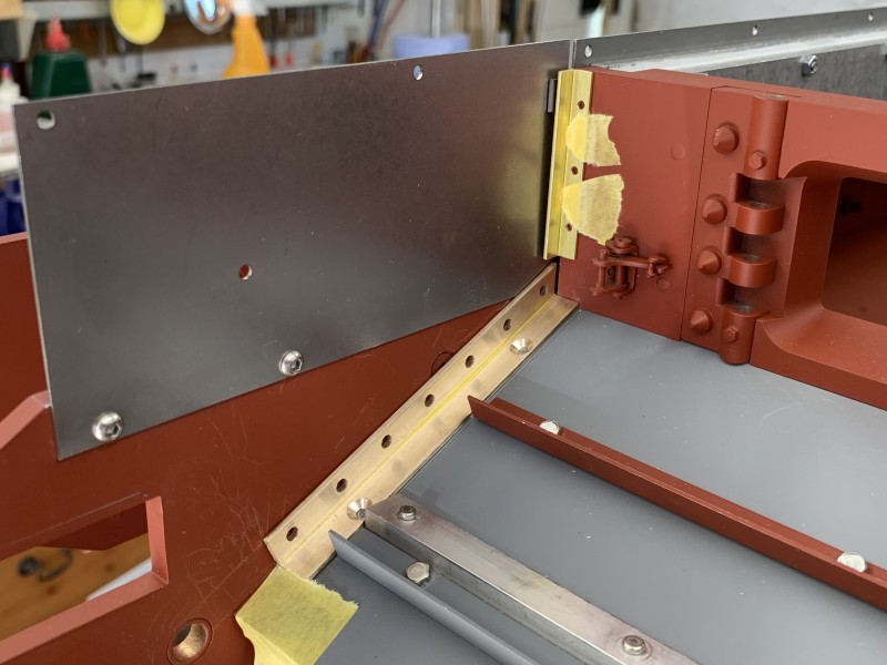
- Front upper and glacis plate detailing
Re: Churchill Mk3 number 67
Posted: Fri Jun 30, 2023 5:23 pm
by Gary Richardson
Hi all
Additional photos of the upper front and glacis plate mods. I have also started drilling the side plate for the rivets and will be using five M2.5 bolts to secure it instead of the two M3 button heads. Lots more rivet holes to drill along the top which form a staggered line, the rivets will be 1/16" copper dome heads.
Regards
Gary
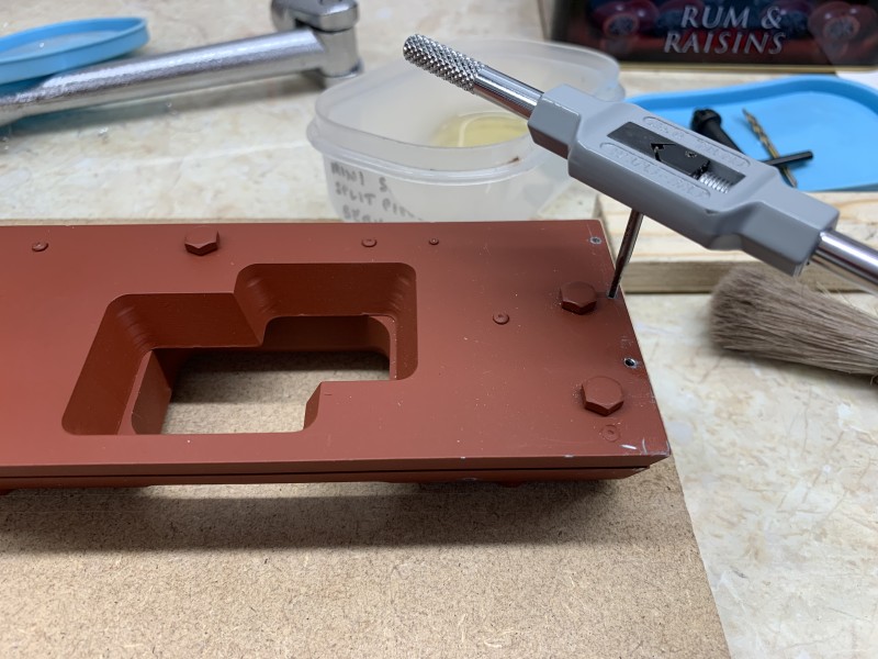
- M2 tap being used
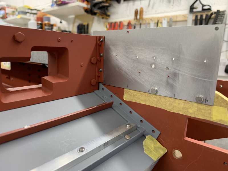
- Lots of holes required
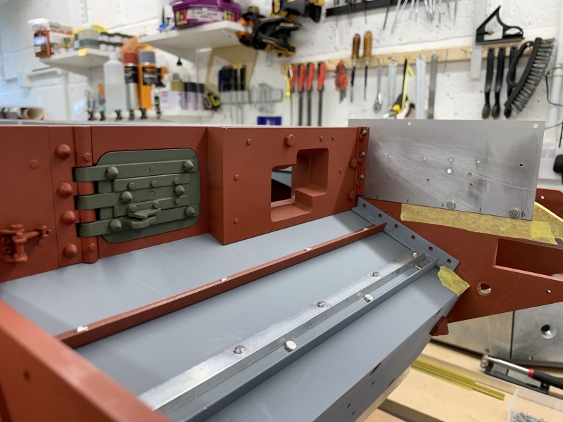
- M2 and 10BA bolts in place
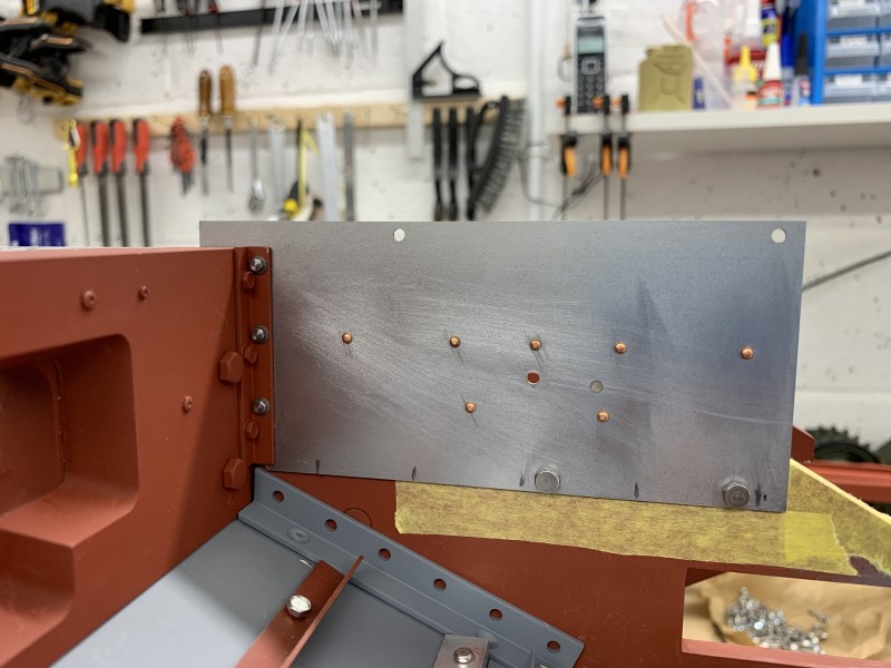
- Half the rivet holes completed
Re: Churchill Mk3 number 67
Posted: Tue Jul 04, 2023 6:06 am
by Gary Richardson
Good morning
Yesterday I completed drilling the 1/16" rivet holes along the top of the side plate, the rivets are copper dome heads and are a tight interference fit.
I used a nail punch the same size as the rivet head held in a vice to rest the rivet head in, then having cut the rivet close to the plate tapped the reverse of the rivet flat. The rivet placings were taken from various photos and are my best guess within the realms of full size and model design differences.
Although there are still a lot of modifications I could do to the idler horns I need to get the panniers attached to the hull. I am running out of space on the work benches as modified/ completed parts accumulate. To this end I started spraying the insides of the panniers matt white. It is surprising just how long the hull of the Churchill is, especially once the panniers and idler horns are attached. The panniers only just went into my spray booth and I suspect the aircraft hanging from the garage ceiling have gained a layer of white dust.

Regards
Gary
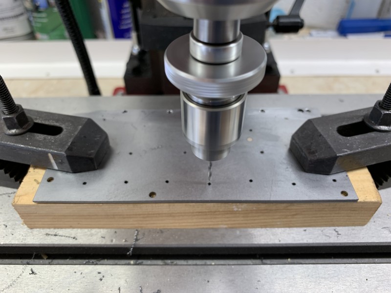
- On the top line four of the rivets are staggered
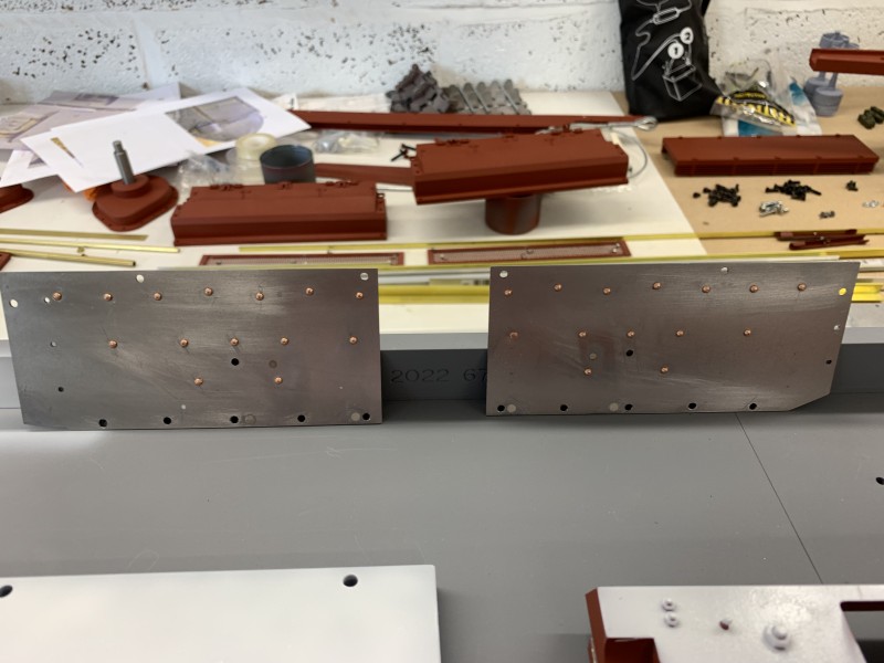
- Copper dome head rivets
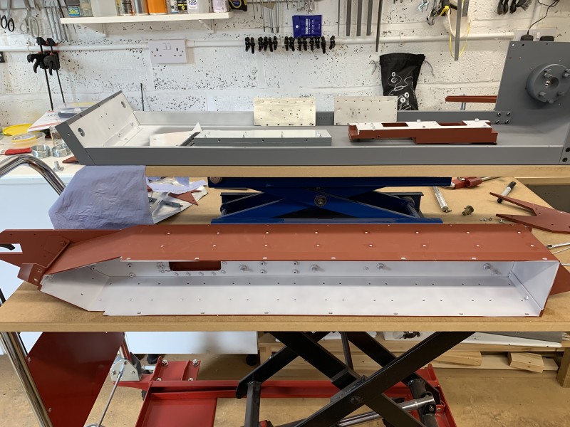
- Spraying the internal areas matt white
Re: Churchill Mk3 number 67
Posted: Sun Jul 09, 2023 9:15 pm
by Gary Richardson
Hi all
The last few days have been spent priming all the components that make up the hull. Those that will be hard to spray are being top coated as well. I solved the problem of opening the pannier hatches which are very stiff, I adapted a 55 year old relay spring adjusting tool from my telecoms apprenticeship days. The metal is extremely tough and the mill struggled but I managed to reshape the tip, drill a 1.5mm hole and silver soldered a hardened steel pin in place. The pannier hatches had a suitable hole drilled in the side at a 25 degree angle and it all works very well. Now I can put whatever switches I want behind the hatches.
While waiting for the primer to dry I had a go at making a metre of barbed wire using 0.6mm galvanised wire. The two lengths of wire were twisted together using an electric drill at one end and the other ends held in a vice. It is quite time consuming to do all the barbs but I am pleased with the result. The wire will be used with the Churchill for display purposes, either as a roll on the tank or as a stand alone barricade with suitable wooden cross members. Having managed to get snagged on it I can confirm it works as per full size.

Regards
Gary
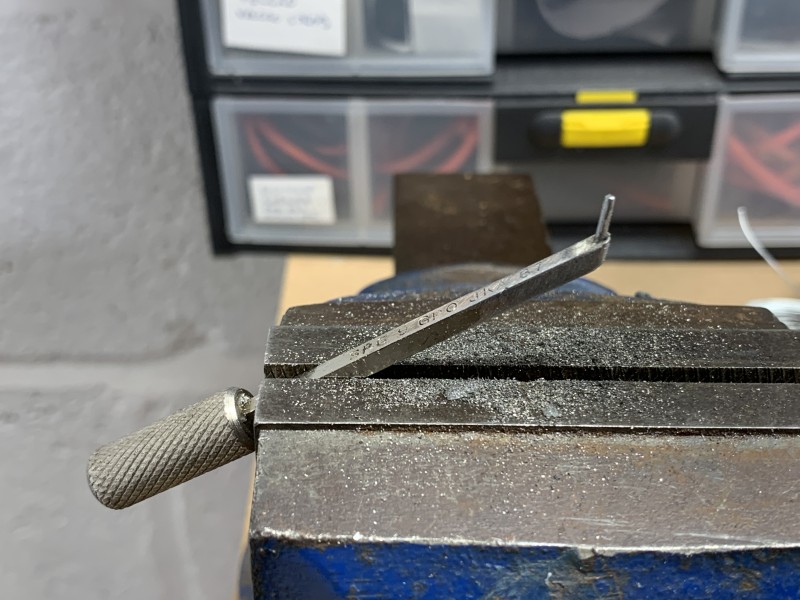
- Adapting a spring adjuster
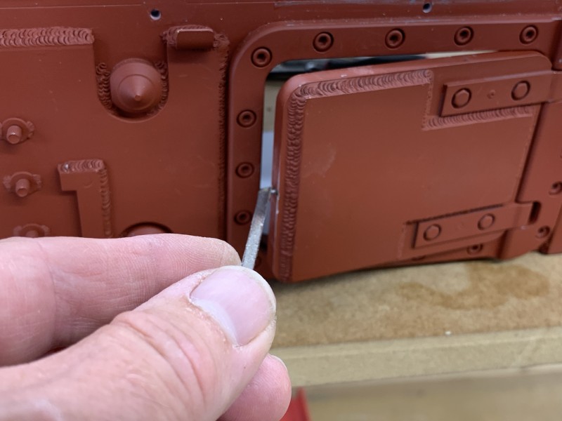
- Hatch tool in action
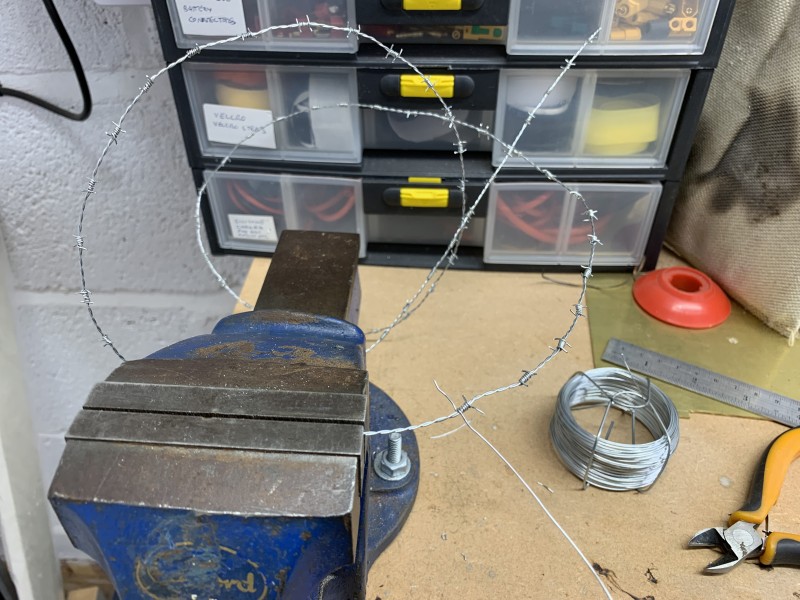
- 0.6mm galvanised wire
Re: Churchill Mk3 number 67
Posted: Mon Jul 17, 2023 8:34 am
by Gary Richardson
Good morning all
After a weeks delay looking after Rosy the guide dog puppy

I have made progress on the hull of the Churchill. I have added one of the panniers and the front shield I had been working on. The pin has been put in the drivers visor after enlarging the visor hinge holes to allow it to sit flush.
Last night I ordered the batteries and am going to try the Yuasa REC22-12i which are meant to have better and longer deep cycling properties to the standard Yuasa REC22-12 batteries due to oxygen regeneration ( I don't understand it either). There is only a few pounds difference in price and they are becoming easier to get.
Once the batteries arrive I will work out how to place then in the hull before adding the second pannier. When Steve showed me his Churchill there seemed to be very limited space for the positioning of the batteries and he had to put them right to the front which meant they were directly below the front hatches with very little clearance below the hatch. This could be a problem as I want the controls for the 8 ton derrick to be under the drivers hatch as per full size, plus due to the weight of the derrick, I need them a bit further back.
I have just measured the internal height of the panniers and there is room for the batteries to use that space as well so I will let you know how I get on.
Regards
Gary
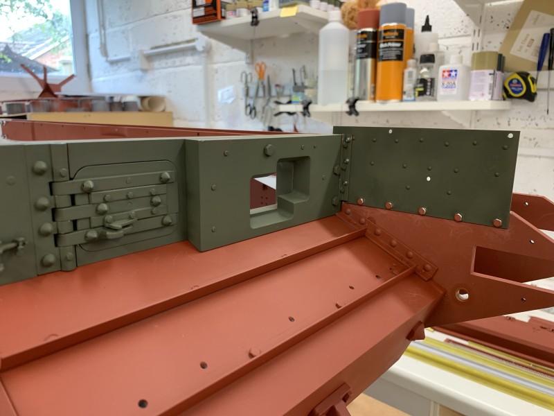
- Visor pinned and shield bolted in place
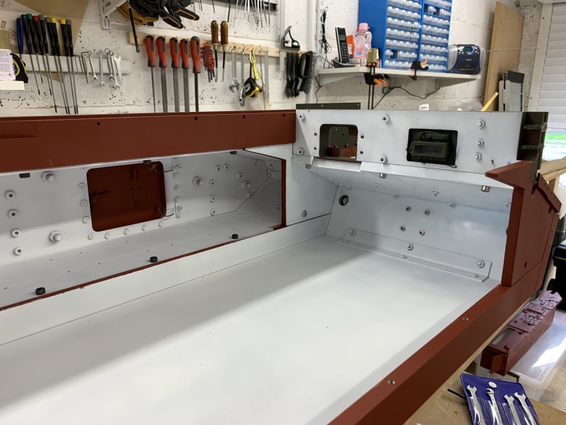
- Now for the battery location to be decided
Re: Churchill Mk3 number 67
Posted: Wed Jul 19, 2023 9:08 am
by Gary Richardson
Hi all
Not too much done on the Churchill yesterday as messing about with the van planning how to secure the tanks. I also took the liner out which has taken up a large amount of room in the garage. The Yuasa batteries arrived very promptly so I was able to try a couple of battery locations. I am hoping to be able to sit them partially in the panniers as per the photo. I have also sent an e-mail to Armortek to obtain the option packs. Without the options I cannot arrange the battery positions but if the pannier plan works I will have space for the driver and switch gear for the derrick. I may be able to move the batteries back slightly depending where the slip ring sits under the turret.
Regards
Gary
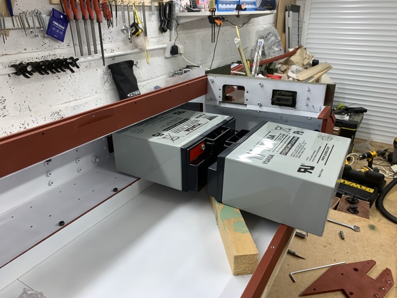
- One possibility
Re: Churchill Mk3 number 67
Posted: Wed Jul 19, 2023 10:20 am
by Vince Cutajar
Gary
Normally Armortek might send a battery tray with the motion pack. So that might give you more options. Having said that it might not send a tray if the Churchill does not have torsion bars.
Also, apart from the slip ring, you might find that the turret traverse motor might affect the position of the batteries.
Vince
Re: Churchill Mk3 number 67
Posted: Thu Jul 20, 2023 7:42 pm
by Gary Richardson
Vince Cutajar wrote: ↑Wed Jul 19, 2023 10:20 am
Gary
Normally Armortek might send a battery tray with the motion pack. So that might give you more options. Having said that it might not send a tray if the Churchill does not have torsion bars.
Also, apart from the slip ring, you might find that the turret traverse motor might affect the position of the batteries.
Vince
Hi Vince
I completely forgot about the turret traverse motor

, I will wait until I get the option packs and see what room there is .
Regards
Gary
Re: Churchill Mk3 number 67
Posted: Thu Jul 20, 2023 7:51 pm
by Gary Richardson
Hi all
A quick update on the barbed wire I made. I put the wire in a container of lemon juice for a couple of days, the lemon juice was out of date and sitting at the back of my cupboard and I didn't have any vinegar handy. I then put the barbed wire into a plastic bag with a small amount of water and left it in the garden for two days. I am pleased with the patchy rust effect, I have used matt varnish to seal the rust in place.
The barbed wire will either be used as a roll on the Churchill or I will make a wooden barbed wire barricade to sit next to the tank.
Regards
Gary
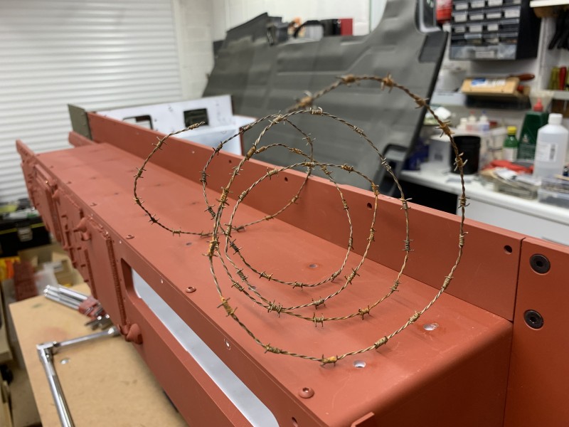
- One metre of rusty barbed wire
Re: Churchill Mk3 number 67
Posted: Sun Aug 06, 2023 8:28 am
by Gary Richardson
Good morning
I have had a weeks break from doing the Churchill as a new toy arrived, I finally got a lathe

. I also bought the metal cabinet for it to sit on, unfortunately the floor of the garage is on a slope where the lathe is to be sited so I had to make a level mortar base for the cabinet to be bolted to.
Hence the weeks delay while I wait for the mortar to fully cure before drilling it.
I have started assembling the lower hull and have attached both panniers, the insides of the panniers and hull have been painted matt white. Both front side screens have been attached using scale size bolts and I am ready to turn the hull upside down to add welds and put on the topcoat of paint.
The final drive and gear casings have been added. The gears have been coated with dry lube.
I should also be able to get the various modules soon after Monique gave me a timeline, this will allow me to plan the wiring/charging looms. Monique confirmed that Kian is going to produce the machine gun smoke system and it will be available for the Churchill so I like the idea of that. I think it adds a dimension the public will enjoy, especially children.
I have been thinking about modifying or making a new machine gun mount so it can swivel left and right as well as up and down but I will wait until I get the packs and get a better idea of how much room I will have once the batteries are installed.
Regards
Gary
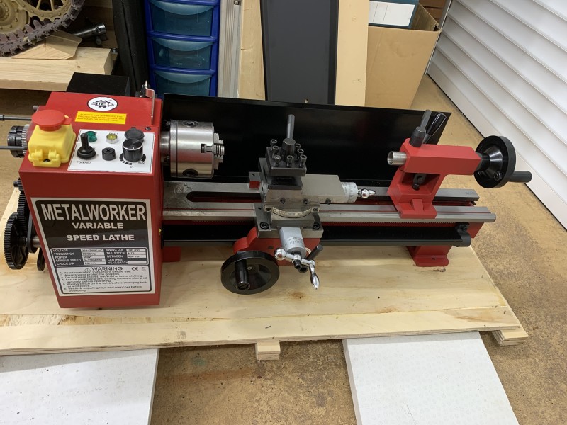
- Sieg SC3 mini lathe acquired at last
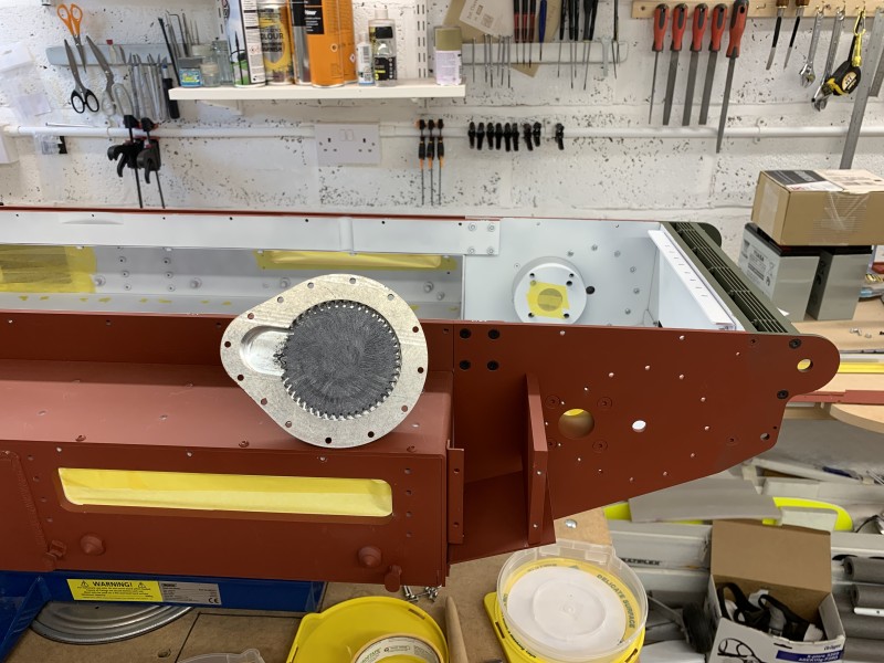
- Dry lube used on the gearing.
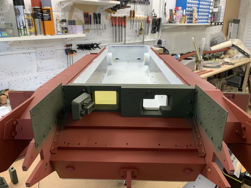
- Both front shields bolted in place
- Some Armorpax goodies from Dave
Re: Churchill Mk3 number 67
Posted: Sun Aug 06, 2023 10:28 am
by Vince Cutajar
Nice new toy.
Hope you don't fall into the machining rabbit hole.

Vince
Re: Churchill Mk3 number 67
Posted: Sun Aug 06, 2023 3:48 pm
by Gary Richardson
Vince Cutajar wrote: ↑Sun Aug 06, 2023 10:28 am
Nice new toy.
Hope you don't fall into the machining rabbit hole.

Vince
Hi Vince,
Will watch out for that hole

. I am going to start with a few easy mods such as the 5mm track pins without the knurled ends that Adrian Harris has made. They make it easy to break the tracks into manageable sections in the field. The main reason for buying it is to make the Petard mortar and associated equipment inside the turret. I want to make it fire the 'dustbin' using either compressed air or CO2 but need to work out the best method.
It will also come in handy when I start on the 8 ton Derrick.
Best wishes
Gary
Re: Churchill Mk3 number 67
Posted: Sun Aug 06, 2023 9:17 pm
by Vince Cutajar
Re: Churchill Mk3 number 67
Posted: Thu Aug 10, 2023 12:49 pm
by Gary Richardson
Good afternoon
The preparation and spraying of the lower hull is proceeding well. I decided to use Milliput welds to seal any joins in the lower hull after roughing up the weld areas with a knife using a cross cut pattern. I used this method on the Tiger and so far all the welds have remained intact.
Some of the areas might not have been welded on the full size but very few will be seen once the bogies and tracks are on and I would rather keep moisture out of the hull.
So far the hull has had two coverings with the spray gun and I will give it one more after those have dried out.
There are a couple of things I found while attaching the panniers which might help others building the Churchill. Both of the Upper Hull strips EX105 and EX105M were bowed and I was unable to remove the bow despite several attempts. This also affects the deck alignment making it difficult to line up with the fixing holes. When I installed the panniers I left the M4 x 6 fixing bolts loose then used a clamp to pull both the hull strips in to remove the bow. The bolts were tightened with the clamp in place and solved the problem. At the same time you can check the deck hole alignment and tweak it if necessary.
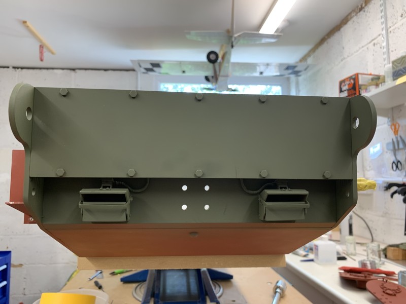
At this stage of the build the hull has become too heavy for me to turn over, and that's without the bogies on. Mind you, I have added a lot of extras so far such as the applique armour. With that in mind can anyone confirm what the fours holes in the floor plate are for, I am assuming it is to attach one of the modules ( smokers ?) but I haven't got my modules yet and I don't want to guess.
Regards
Gary
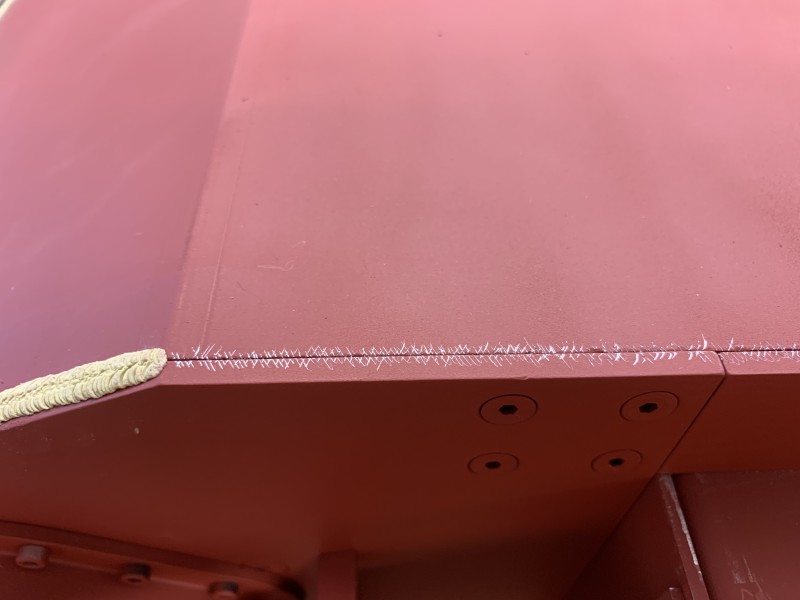
- The cross hatching helps the Milliput stay in place
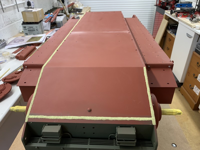
- Lots of welds, I did tidy up the nearest one.
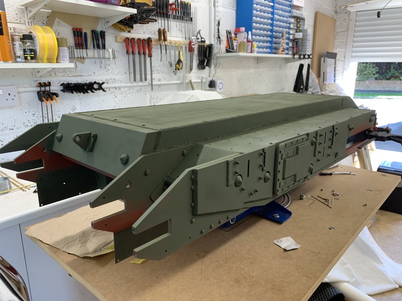
- second coat being applied
Re: Churchill Mk3 number 67
Posted: Sun Aug 13, 2023 2:08 pm
by Gary Richardson
Good afternoon
I have turned the hull the right way up having completed the welds, topcoat and matt varnish coat on the underside. The panniers have had the welds applied and have been sprayed which was much quicker now I have sourced a 0.5mm needle set for the Eclipse air brush. The drive wheels/sprockets have been fitted and run freely. This did take a while as the left hand set up needed some fettling and tweaking to get everything aligned correctly.
The outside bearing has not been Loctited to the shaft as that would have made it impossible to remove the rear plate. Both sets of track slides have been attached to the tops of the panniers along with the mod at the front to stop them bowing up. Having got this far I can see there is little scope for doing a quick field repair/adjustment to the drive assembly, the track slides stop access to the front two nuts holding the rear plate in place. It might be possible to silver solder the nuts to the bracket at the rear of the pannier negating the need to access them, this would simplify access to the drive sprockets etc.
I have temporarily added the front sprockets to check the alignment, I want to add some detail to the track adjusters to make them more like the full size. Nothing too elaborate as the horns are already fixed in place with a lot of Milliput welds.
I intend to make a working tow hook possibly with the cable release as per full size , this could be servo operated. It will need to be robust enough to allow the tank to tow the 8 ton derrick which is going to be 1.4m long and at present I do not know the weight although the rolling resistance should be quite low. I hope to make most of the tow hook components using the mill, I would welcome any suggestions from those of you with engineering experience, as to the best metals to use for ease of machining but also strength, especially the hook which will need quite a bit of hand filing to get the correct shape.
Regards
Gary
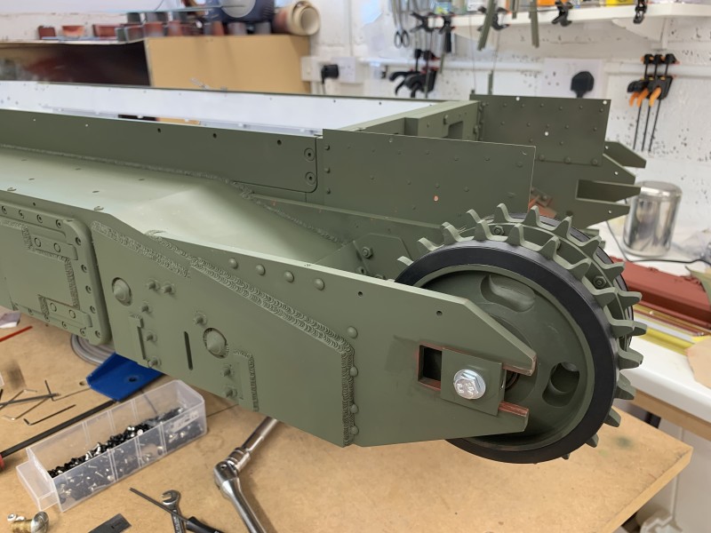
- Front sprocket alignment check
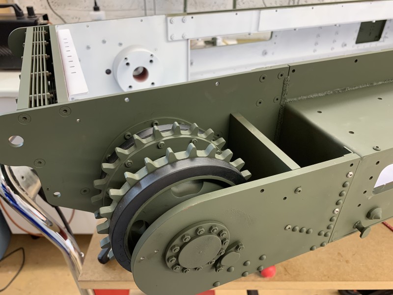
- First dry fit to check alignment and free wheeling
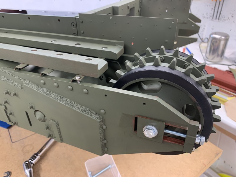
- Needs some detailing
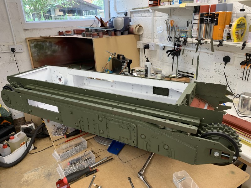
- Beginning to take shape now.
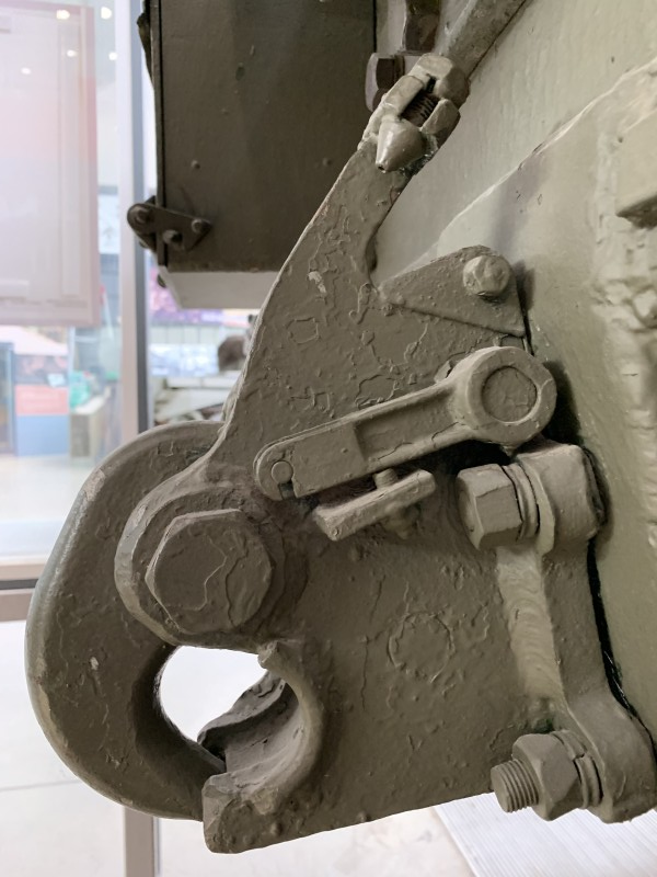
- Photo courtesy of the Tank Museum
- mzavwp9o.png (600.48 KiB) Viewed 4269 times
