Page 1 of 3
Chieftain Mk 5 Guide
Posted: Tue Oct 01, 2019 2:16 pm
by Stephen White
This is a copy of the guide to Chieftain, which I wrote for Kian and Mark before they began the design of the model. It is a quick summary of the main visual recognition features of a typical Mk 5 which is the basis for the kit. It's posted as written, the references are to particular tanks in the Tank Museum collection. Sod's Law dictates that no plan survives first contact. In this case, the only representative Mk 5 in the collection was shipped to the Netherlands the day before we visited, without us being told. Still, flexibility is a quality of armoured soldiers, so we found the bits we wanted on other vehicles. It may be a poor pun on British tank names but that day really impressed me with the challenge and skill required to capture such a complex object, the turret casting in particular. To say I was impressed suggests I could understand the process, which is far from the truth. I hope this guide is useful.
Re: Chieftain Mk 5 Guide
Posted: Tue Oct 01, 2019 5:39 pm
by John Clarke
This will be a god send topic. I was reluctant to start one, as there's nothing as frustrating to "those in the know" than "those that don't know" the "B" obvious.
So I'll start with these two annoying thingy ma bobs I'm trying to get a my head round.
Is that a fan cowling, part of the air con

(There was no Air Con un less you open a hatch) and what were the slots for on the bazooka plates, (guessing for lifting and positioning)
And is it good army "PC" to have Grunt Crusher on the side of your vehicle?
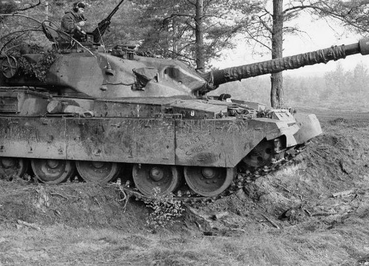
- 02d69a081b46ee38f37ff94576a9b663--british-tanks-british-army.jpg (99.34 KiB) Viewed 4756 times
Re: Chieftain Mk 5 Guide
Posted: Tue Oct 01, 2019 6:53 pm
by Mark Heaps
I stand by to be corrected by Stephen White or John Heaps who actually crewed them but I suspect the following.
Circular armoured plate plus ducting - Allows cabling to be fitted for the dozer-blade attachment. Some but not all Challenger 1´s had an almost identical plate on the front hull and that was what they were for. Challenger 1 Sqn 2iCs tank always had it, some other random tanks also had it
Slots in bazooka plates - points to clip / hang the crew shelter on. I cannot imagine any other use or need for them.
Mark
Re: Chieftain Mk 5 Guide
Posted: Tue Oct 01, 2019 7:57 pm
by Stephen White
Glad it's of use.
The slots in the bazooka plates are to allow the crew to check track tension without removing the plates.
I don't know the purpose of the circular duct and channel on the hull side. It never entered our daily lives, so was ignored, as far as I know. I've checked the tech pubs for the dozer and it isn't related. I then thought about turret breathing, the ability to feed the main engine air breathers from the turret, when the normal feed through the engine decks was subject to water or dust ingress. The routing is all internal so rules that out, as is the ducting for air for the fighting compartment drawn through the NBC filter.
Someone will come up with the answer.
Re: Chieftain Mk 5 Guide
Posted: Tue Oct 01, 2019 8:18 pm
by Mark Heaps
Hi Stephen,
The slots are approximately where the three top rollers would be so are of no use whatsoever for checking track tension. Track tension needed to be checked at the mid point between two of the top rollers ( I seem to remember the first and second ) and I believe the general rule of thumb was that if you could just insert a clenched fist between the track and hull then it was good.
Mark
Re: Chieftain Mk 5 Guide
Posted: Tue Oct 01, 2019 9:01 pm
by Stephen White
You can have that one mark, since it”s REME’s 77th birthday today. Not many know that.
Re: Chieftain Mk 5 Guide
Posted: Wed Oct 02, 2019 12:51 pm
by John Clarke
So we think the curious thing on the R/H side may be a ducting of some sort?
Found a picture with the cover removed if it's any help.
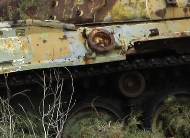
- 2345.jpg (47.99 KiB) Viewed 4630 times
Two more unknowns to me.
What is the runner for by the side of the commanders hatch for, with two metal blocks welded to the turret?
And what are these tubular fittings for?
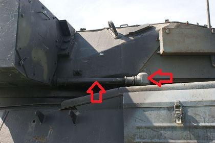
- kru_17.jpg (71.62 KiB) Viewed 4630 times
Re: Chieftain Mk 5 Guide
Posted: Wed Oct 02, 2019 1:20 pm
by Stephen White
Last photo shows the cable duct for the the light projector, including power for the lamp and control of the outer door and IR filter, which could be opened and closed to select IR of white light.
Fittings on turret roof are something Mark will have to comment on. I haven’t a clue.
Re: Chieftain Mk 5 Guide
Posted: Fri Oct 04, 2019 8:01 pm
by John Clarke
Hope these two bits are easier to identify.
An Ariel base some times covered and an extended cable cover? The other, a large plate maybe a ventilation cover? There's a gap at one end
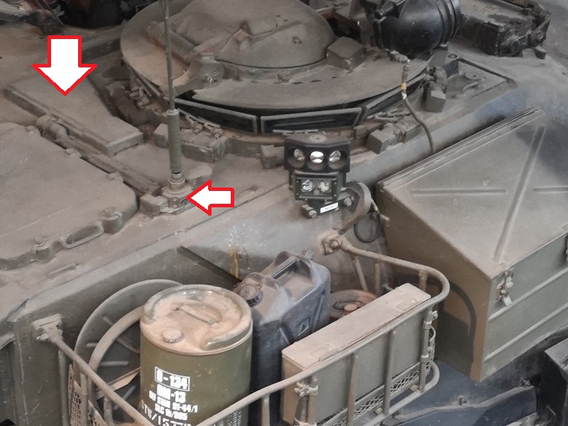
- 78896.jpg (137.73 KiB) Viewed 4532 times
Re: Chieftain Mk 5 Guide
Posted: Sat Oct 05, 2019 11:10 am
by Stephen White
Armoured cover is the Pressure Relief Valve Cowl. It's described as an "armour ballistic cowl" protecting the outlet aperture of the NBC pressurisation system pressure relief valve.
Apparent antenna is the IR Detector Stalk, which contained three photo-electric cells intended to provide indications to the commander via a control box that the tank was being illuminated with IR light. It was rarely seen fitted, an item that firmly remained in storage, since it was vulnerable to damage and of little practical use. Good idea at the time but about as much use as a chocolate ash-tray. It presaged the modern concept of defensive aids suites which are infinitely more effective across a range of electronic and visual threats. I believe I've covered this in another thread.
Re: Chieftain Mk 5 Guide
Posted: Sat Oct 05, 2019 2:02 pm
by Mark Heaps
No idea what the two blocks welded to the turret were for but may know what the rail /runner / gutter was for. If Stephen, John or another crewman can confirm it was never to be repainted but always masked off if re-painting that part of the turret then I can say for certain.
Mark
Re: Chieftain Mk 5 Guide
Posted: Sat Oct 05, 2019 3:30 pm
by Mark Heaps
John Clarke wrote: ↑Wed Oct 02, 2019 12:51 pm
So we think the curious thing on the R/H side may be a ducting of some sort?
Found a picture with the cover removed if it's any help.
2345.jpg
Does not look like a cable duct as I originally thought. Looks more like a duct and filter housing for hydraulic fluid. Did the dozer fit on Chieftain require a hydraulic supply from the gearbox?
Mark
Re: Chieftain Mk 5 Guide
Posted: Sat Oct 05, 2019 4:47 pm
by Mark Heaps
The NBC system, ( New Beer Cooler in peacetime, Nuclear, Biological, Chemical in wartime ) over-pressurised the air in the vehichle so any leaks in the vehicle would result in air being pushed out keeping contaminants at bay rather than contaminated air leaking in. After firing the main armament, the breech was open so a big hole to the outside. A good loader would have and should have then slapped the next projectile and bag-charge in and closed the breech to seal the hole. If the loaded projectile was the wrong type for the next target, so what, fire it off and load the needed type.
Re: Chieftain Mk 5 Guide
Posted: Sat Oct 05, 2019 5:05 pm
by Stephen White
So we think the curious thing on the R/H side may be a ducting of some sort?
Found a picture with the cover removed if it's any help.
2345.jpg
Hydraulic conduit no, electrical yes......
The dozer blade hydraulic power pack was fitted to the track guard in lieu of the front right bin. The hydraulics were self contained, wholly outside the vehicle. Electrical power to the power pack was tapped from the Battery Master Switch box inter-vehicle socket (ie where you plugged in a jumper lead). The control box for the blade was inside the driver's cab. The dozer power supply harness and the control cable were routed internally and exited the hull via.................... an armoured cable outlet on the hull side. See this extract from the relevant EMER:
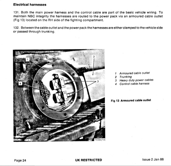
- Dozer cable conduit.jpg (75.26 KiB) Viewed 4376 times
Just the top of the turret objects to crack now.
Re: Chieftain Mk 5 Guide
Posted: Sat Oct 05, 2019 6:12 pm
by Mark Heaps
Glad to get confirmation that the conduit on the right hand side of the hull was for the optional dozer fit as I suspected.
Now for the turret "rail".
Tanks were "bore-sighted" before firng. Muzzle, sights and MRS lamp being aligned. Fine as long as the gun and sight were elevating and depressing parallel. If they were not then you got inaccuracies, ie going right above the bore-sight elevation and going left below it or vice-versa.
If a tank consistently failed CABF ( Confirmation of Accuracy By Firing ), and we could not immediately determine a cause then it went "over the bridge"
It did not require an ECE to be dragged away from the firing point for the length of time required so I have to rely on what the gun-fitter told me at the time. The "rail" on the top of the turret was a fixed machined datum point ( that is why I asked for confirmation from a crewman that it was never painted over ). There was also a machined datum point on the gun breech. The tank would be driven over a tank bridge to get the gun at full elevation and depression and stopped at multiple positions. At each position a clineometer would be placed on the turret datum and the breech datum, the results recorded and later correlated & evaluated.If the gun showed deviations whilst elevating/ depressing then there was maybe a problem or free-play with the gun-mount that they needed to fix. If the gun mount was proved to be okay then they would shim the sight mounts to get the sights operating parallel to the gun.