Hi Marcus.
Excellent work on your 25pdr Gun Shield.
Lot's of nice details on the outside and inside the of the shield.
Certainly plenty of rivets everywhere….
I might need to buy more rivets as I keep pinching them for my upgrades on my Limber kit!
Looking forward to your next instalment on your 25pdr……..brake system and whatever!
Cheers
Ian
Marcus's 25 pounder
-
Ian Rodney
- Posts: 480
- Joined: Thu Jul 05, 2012 6:39 am
- Been liked: 53 times
-
Dave Backway
- Posts: 103
- Joined: Mon Oct 06, 2014 6:27 pm
- Location: Exeter, Devon
- Has liked: 12 times
- Been liked: 55 times
Re: Marcus's 25 pounder
Hi Marcus,
As always impressive work on the 25 pounder, I was wondering how you managed to get the rivet head showing on both sides of the gun shield along the strengthening angles?
Best regards
Dave
As always impressive work on the 25 pounder, I was wondering how you managed to get the rivet head showing on both sides of the gun shield along the strengthening angles?
Best regards
Dave
-
Marcus Kwa
- Posts: 176
- Joined: Wed Nov 13, 2013 6:22 pm
- Been liked: 39 times
Re: Marcus's 25 pounder
Years have passed since my last post and to be honest nothing much has happened with regard to my 25 pdr (apart from my Pheasant that is...)!!
But I have not been idle, I have acquired a new skill: soldering!!
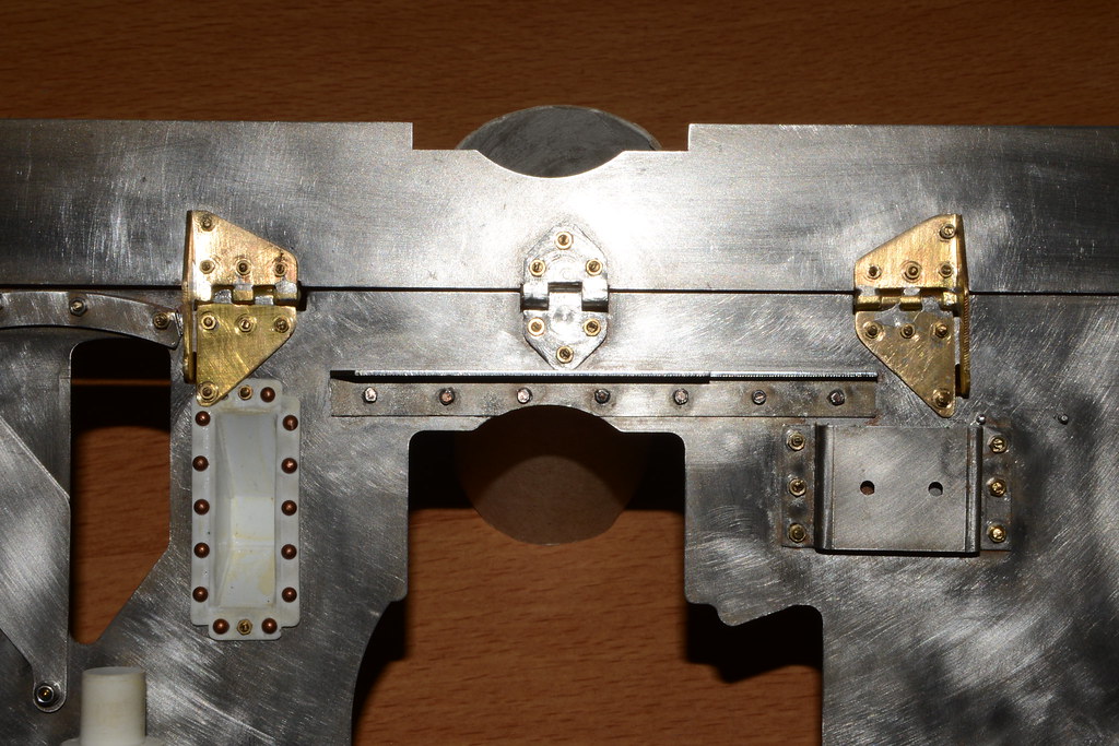
The first real use was soldering together a new set of hinges for the movable upper part of the gun shield. In an earlier post I had made these from styrene, but on a model this size it is hardly strong enough, especially on working/moving parts. And after having repaired them for the third time the styrene had to go: enter brass!
Soldering is not very difficult and though cutting or sawing parts from brass takes longer, I found that securing the parts to be welded during the soldering process is the real challenge. By the way I use a torch to heat up the parts and solder (next will be resistance soldering).
The parts were cut from brass sheet 1mm thick and brass tubing. The upper parts of the hinge (with the securing arms) were cut from an angle line to safe one weld.....
The slewing platform of the gun was next, this was a real challenge since the area to be heated is quite large. I compromised by soldering it in sections and not the whole circumference is actually soldered. I unfortunately did not take any photographs of the finished platform and it has since been covered by (etch) primer . Only addition was a (brass) flange on the upper ring.
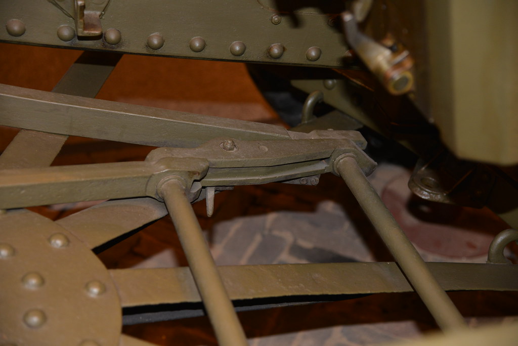
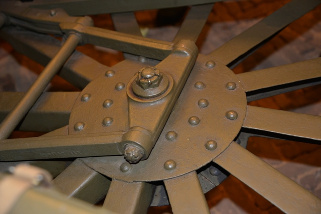
Another part of the slewing platform That I modified were the positioning arms keeping the gun aligned when on it. In the kit these are represented having two hinged sections where the actual piece has 3 hinged sections. The kit section closest to the rotation point was modified to have an extra hinge. Also the middle of the 3 sections on the real gun has a very particular shape and cross section. Also note that the connection of the arms to the rotation axis is offset where the kit has it centered :
The brass version, with the replaced kit parts:
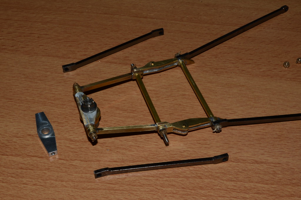
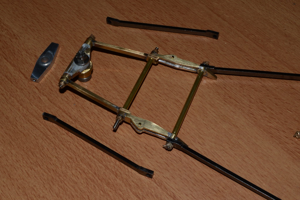
The middle arm section was build up from an upper and lower plate (1.5mm thick) sandwiching a 3mm thick filler plate (1mm narrower all around) thus forming the distinctive I beam cross section. The longest of the arm section in the photo are still the kit parts but will be replaced by brass next.
The nuts were replaced by castellated ones.
That's it for now!
Cheers,
Marcus
But I have not been idle, I have acquired a new skill: soldering!!
The first real use was soldering together a new set of hinges for the movable upper part of the gun shield. In an earlier post I had made these from styrene, but on a model this size it is hardly strong enough, especially on working/moving parts. And after having repaired them for the third time the styrene had to go: enter brass!
Soldering is not very difficult and though cutting or sawing parts from brass takes longer, I found that securing the parts to be welded during the soldering process is the real challenge. By the way I use a torch to heat up the parts and solder (next will be resistance soldering).
The parts were cut from brass sheet 1mm thick and brass tubing. The upper parts of the hinge (with the securing arms) were cut from an angle line to safe one weld.....
The slewing platform of the gun was next, this was a real challenge since the area to be heated is quite large. I compromised by soldering it in sections and not the whole circumference is actually soldered. I unfortunately did not take any photographs of the finished platform and it has since been covered by (etch) primer
Another part of the slewing platform That I modified were the positioning arms keeping the gun aligned when on it. In the kit these are represented having two hinged sections where the actual piece has 3 hinged sections. The kit section closest to the rotation point was modified to have an extra hinge. Also the middle of the 3 sections on the real gun has a very particular shape and cross section. Also note that the connection of the arms to the rotation axis is offset where the kit has it centered :
The brass version, with the replaced kit parts:
The middle arm section was build up from an upper and lower plate (1.5mm thick) sandwiching a 3mm thick filler plate (1mm narrower all around) thus forming the distinctive I beam cross section. The longest of the arm section in the photo are still the kit parts but will be replaced by brass next.
The nuts were replaced by castellated ones.
That's it for now!
Cheers,
Marcus
-
Marcus Kwa
- Posts: 176
- Joined: Wed Nov 13, 2013 6:22 pm
- Been liked: 39 times
Re: Marcus's 25 pounder
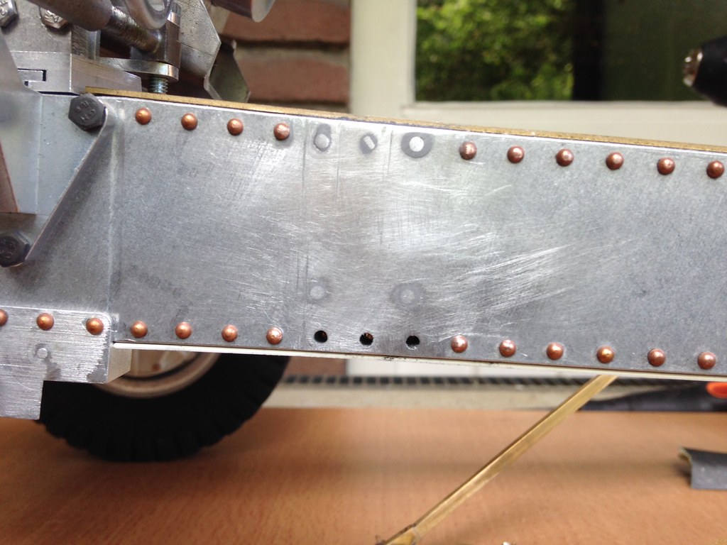
Next part to be made in brass is the gunner seat support. The support was built from 0.8mm thick brass.
I actually made two versions...... The first version used the kit part for basic dimensions and has the connections at the top at the rivet line and the lower connection somewhere just above the bottom rivet line of the trail box. I found out later that the support on the actual gun is attached on the top and bottom row of rivets.......
The good thing was that the second support was built a lot faster than the first one.....
The first seat support, with the same bolt hole arrangement as the kit part:
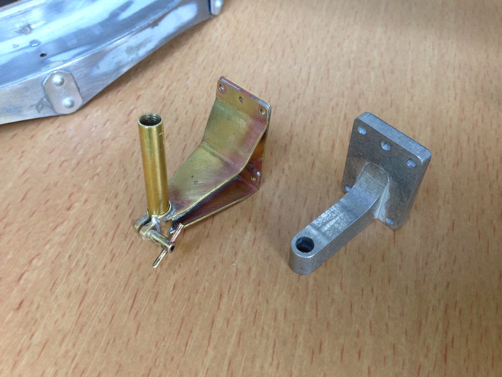
The second support had its backplate made longer to span the distance between the top and bottom rivets:
The support is temporarily fitted into the original bolt holes, these will be filled with aluminium rod later and new holes drilled to fit the rivets on the seat support in line with the rivets on the gun trail (the top of the support has been made with a slight angle since the gun trail is slightly tapered, the rivet on the bottom is a dummy).
Marcus
I actually made two versions...... The first version used the kit part for basic dimensions and has the connections at the top at the rivet line and the lower connection somewhere just above the bottom rivet line of the trail box. I found out later that the support on the actual gun is attached on the top and bottom row of rivets.......
The good thing was that the second support was built a lot faster than the first one.....
The first seat support, with the same bolt hole arrangement as the kit part:
The second support had its backplate made longer to span the distance between the top and bottom rivets:
The support is temporarily fitted into the original bolt holes, these will be filled with aluminium rod later and new holes drilled to fit the rivets on the seat support in line with the rivets on the gun trail (the top of the support has been made with a slight angle since the gun trail is slightly tapered, the rivet on the bottom is a dummy).
Marcus
-
Marcus Kwa
- Posts: 176
- Joined: Wed Nov 13, 2013 6:22 pm
- Been liked: 39 times
Re: Marcus's 25 pounder
The two seat support versions side by side:
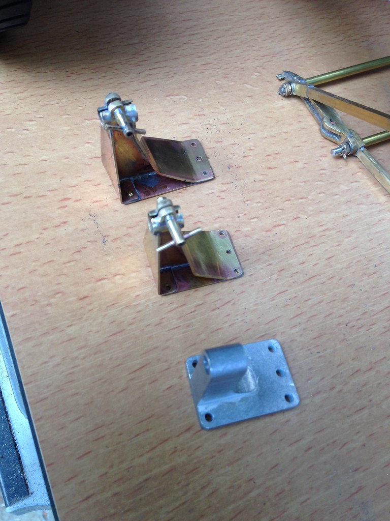
The original boltholes filled:
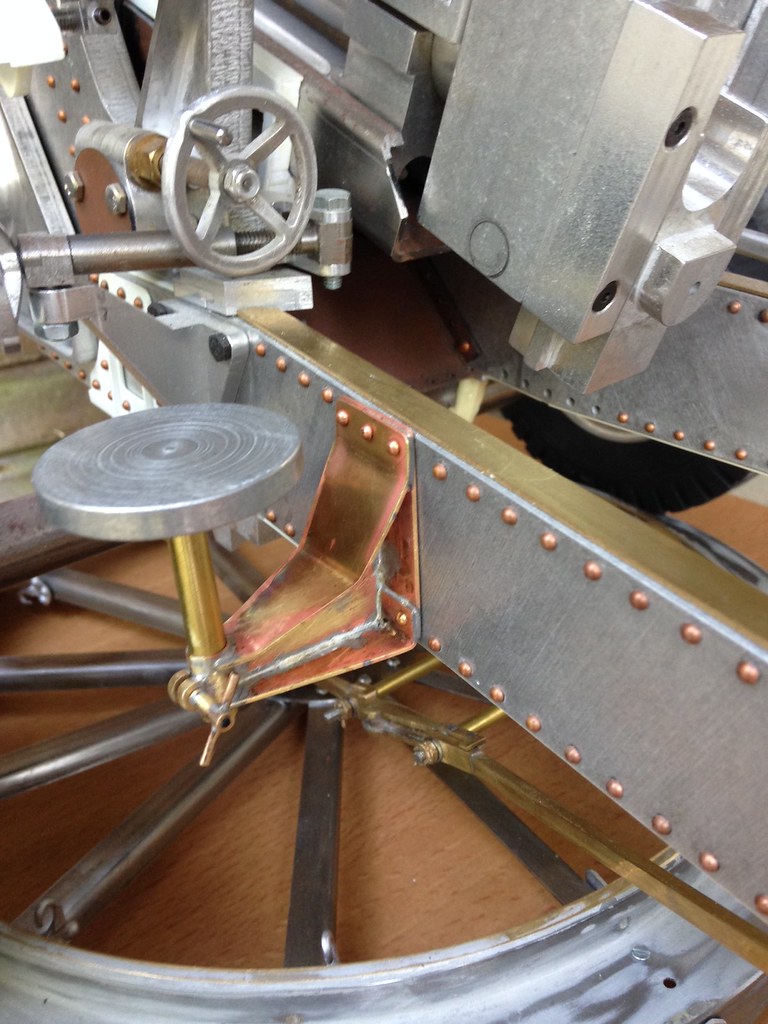
And the seat support on its final position:
Cheers,
Marcus
The original boltholes filled:
And the seat support on its final position:
Cheers,
Marcus
-
Stephen White
- Site Admin
- Posts: 3099
- Joined: Sat Oct 11, 2008 7:05 pm
- Location: Dorset
- Has liked: 974 times
- Been liked: 2044 times
- Contact:
Re: Marcus's 25 pounder
Marcus, that's high quality brasswork.
There are a couple of references to soldering, both conventional and resistance, on the Knowledge Base. I ought sometime to get around to re-writing them as a single topic, when time allows. If you're getting a resistance soldering set, I'd recommend getting both a pair of callipers and an earth wire and probe setup. The best are made by the US company, American Beauty. I think there's a post on it somewhere on the Forum. You'll find the callipers best for small, precise work and the probe best for long joints. With the latter, you can connect the earth with a crocodile clip fitting to the assembly, hold the work in place with rare earth magnets on a steel base and then solder, applying the probe to one side and introducing the solder on the other, leading the solder with the probe. That way, you get a continuous bead. Sorry if this is all familiar to you.
All the best, great build log.
Stephen
-
Marcus Kwa
- Posts: 176
- Joined: Wed Nov 13, 2013 6:22 pm
- Been liked: 39 times
Re: Marcus's 25 pounder
Hi Steven,
Resistance soldering will be the next step, I have a set made by London Road Models. Still have to break it in.
Soldering with a torch has certainly its limitations: soldering to parts that already have been soldered together is a 'challenge'......
But is a lot of fun and the bond is incredibly strong, I was afraid that cutting or sawing the parts would be a problem but with the right saws it is a piece of cake.
Marcus
-
Stephen White
- Site Admin
- Posts: 3099
- Joined: Sat Oct 11, 2008 7:05 pm
- Location: Dorset
- Has liked: 974 times
- Been liked: 2044 times
- Contact:
Re: Marcus's 25 pounder
Marcus, hi. The London Road machine is excellent, it's the one I've been using very happily. I didn't think much of their tools though (the probe soon melts) and found the American Beauty ones much more robust. The AB probe has a very useful heat sink.
Despite the dire warnings on the box, I've found it best to use a high temperature for a short time rather than the opposite. I often use the highest setting but you do have to watch the work carefully to see if the heat is building up too quickly. There are a couple of suggestions to prevent an assembly coming apart with the last piece. Firstly, use heat sinks. I find heavy G-clamps quite useful and I have some 1cm thick steel bars which I use both for work holding and heat sink. The second method is to use a range of solders of differing melting point. I often start assembly with silver solder for example and use softer solder for smaller details. That way, the main assembly never reaches its melting point. Sometimes you just have to allow the whole thing to cool.
For sheet metal work, I've found these to be really useful:
This is the Warco model but there are generic Chinese examples around.
All the best.
Stephen
Despite the dire warnings on the box, I've found it best to use a high temperature for a short time rather than the opposite. I often use the highest setting but you do have to watch the work carefully to see if the heat is building up too quickly. There are a couple of suggestions to prevent an assembly coming apart with the last piece. Firstly, use heat sinks. I find heavy G-clamps quite useful and I have some 1cm thick steel bars which I use both for work holding and heat sink. The second method is to use a range of solders of differing melting point. I often start assembly with silver solder for example and use softer solder for smaller details. That way, the main assembly never reaches its melting point. Sometimes you just have to allow the whole thing to cool.
For sheet metal work, I've found these to be really useful:
- mini-formit-universal-sheet-metal-machine.jpg (25.64 KiB) Viewed 6888 times
All the best.
Stephen
-
Marcus Kwa
- Posts: 176
- Joined: Wed Nov 13, 2013 6:22 pm
- Been liked: 39 times
Re: Marcus's 25 pounder
Ahaaaaaa, I need a larger work bench!!!
Thanks for the tips, Stephen, much appreciated.
Heatsinks, that sounds logical, but would not have thought about that myself! I will study on the different solders, different melting points: got that!
Cheers,
Marcus
Thanks for the tips, Stephen, much appreciated.
Heatsinks, that sounds logical, but would not have thought about that myself! I will study on the different solders, different melting points: got that!
Cheers,
Marcus
-
Marcus Kwa
- Posts: 176
- Joined: Wed Nov 13, 2013 6:22 pm
- Been liked: 39 times
Re: Marcus's 25 pounder
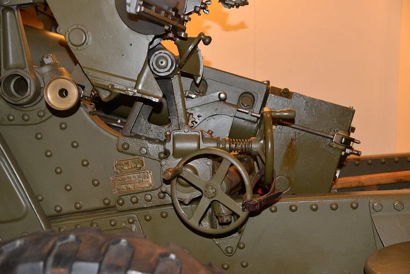
Two types of handwheels are commonly seen on WWII 25 pdr's, the one depicted in the kit with full circular cross section (though the edges of the kit wheels need to be rounded with a file) and a quite similar type featuring a halfround wheel cross section. The kit type wheels also feature slightly inclined spokes, the second type I want to depict have the spokes in a flat plane. The spokes of both types have a T cross section.
Incidentally a third type exists: the short wheel base/split trail (MkIII carriage) 25 pdr's have a smaller 3 spoked traversing/slewing wheel.
The kit type wheels:
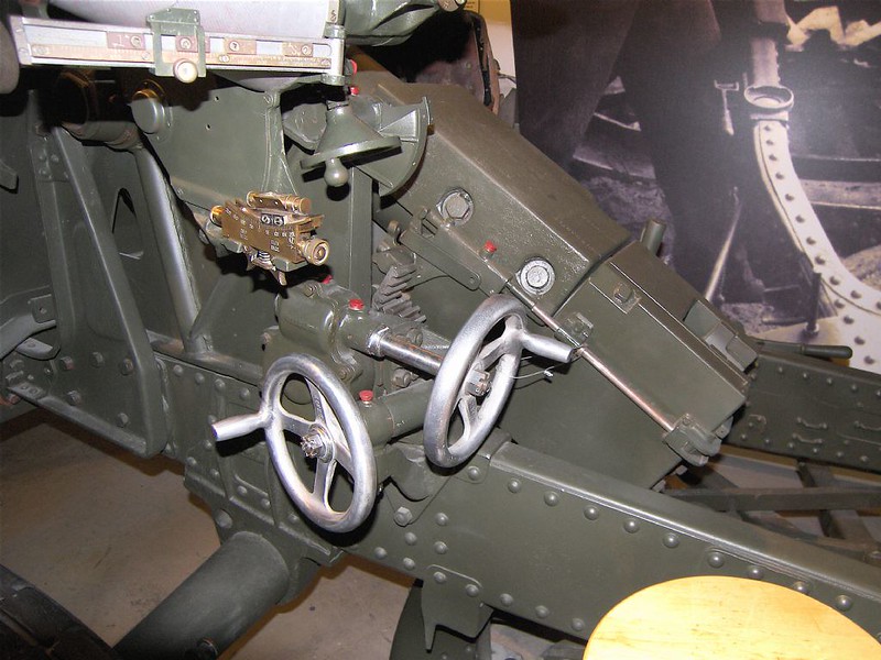
The second type (the example in the artillery museum accidentally has both types):
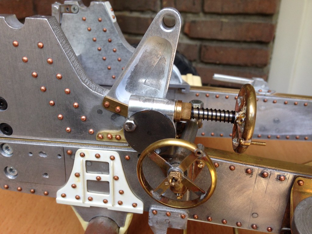
The slewing wheel (front) has the spokes in one plane (halfround wheel rim), the elevation wheel (rear) has dished/inclined spokes (like the kit, full round wheel rim):
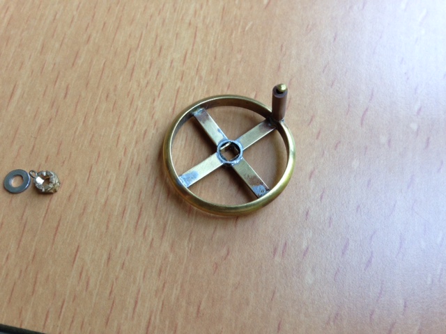
The wheels mounted (handle of one example still needs to be turned from wood):
For the keen observers: I also moved the gunners seat 2 rivets to the rear.
The two brackets behind the gunner seat are for the fuse setting tools/keys pouch.
Next is the brake system and brake lever!
Cheers,
Marcus
Incidentally a third type exists: the short wheel base/split trail (MkIII carriage) 25 pdr's have a smaller 3 spoked traversing/slewing wheel.
The kit type wheels:
The second type (the example in the artillery museum accidentally has both types):
The slewing wheel (front) has the spokes in one plane (halfround wheel rim), the elevation wheel (rear) has dished/inclined spokes (like the kit, full round wheel rim):
The wheels mounted (handle of one example still needs to be turned from wood):
For the keen observers: I also moved the gunners seat 2 rivets to the rear.
The two brackets behind the gunner seat are for the fuse setting tools/keys pouch.
Next is the brake system and brake lever!
Cheers,
Marcus
-
Marcus Kwa
- Posts: 176
- Joined: Wed Nov 13, 2013 6:22 pm
- Been liked: 39 times
Re: Marcus's 25 pounder
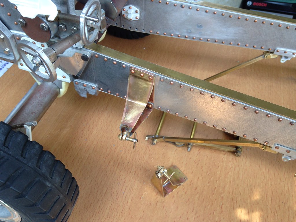
Started with my biggest gamble regarding this build..... The gun traversing and slewing mechanism is positioned to much to the front of the gun. But moving it further aft leaves not much room to bolt everything down. Very likely why Armortek decided to have the kit as it is.
On the original everything is grouped into one casting that is connected with rivets to the cradle, as can be seen in the pics in my previous post.
What's to loose?
So I drilled a new hole to feed the elevating axle through, and replaced the kit parts EJO146 for a brass cog. The gear box was moved such that I could use one of its original boltholes and since the right bolt was now outside the cradle I used a mall locating pin instead. The kit yoke for the traversing arm was fitted where the new axle position is now and had to be re-positioned also ..... It was replaced with a new brass yoke and bolted onto the side of the cradle. The original holes were filled and sanded smooth.
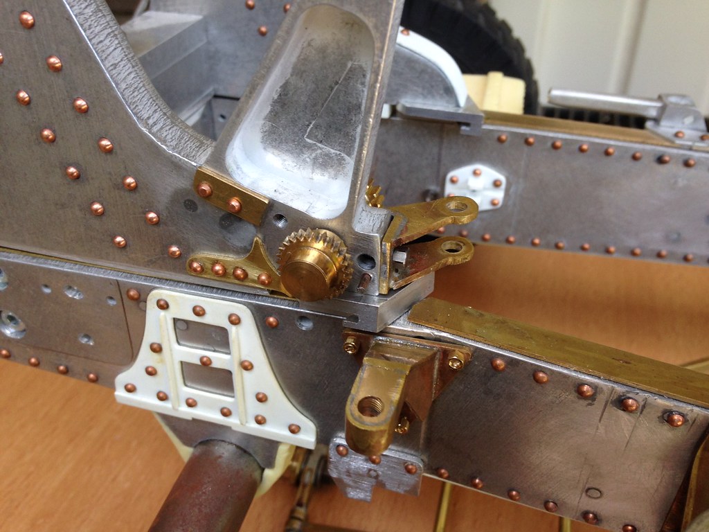
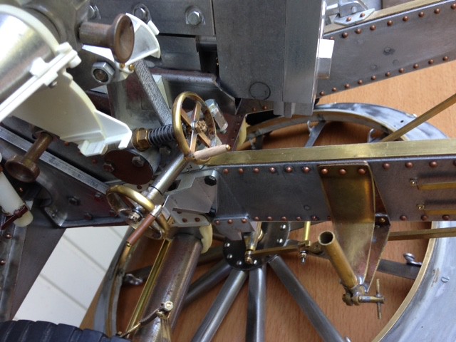
The new cog and traversing yoke (parts are still in 'the rough' and need cleaning and polishing):
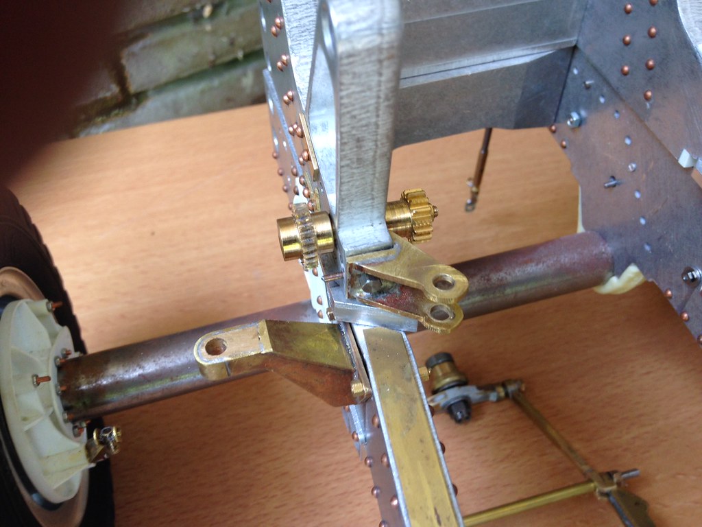
I also had to move the traversing wheel support on the carriage side (kit part EJO160). Though the kit part could have been used (only new locating holes are needed) I replaced the support by a new brass one.......
All parts fitted:,
The gear box will receive some 'massaging' with a file to let it resemble the original more but that is for later.
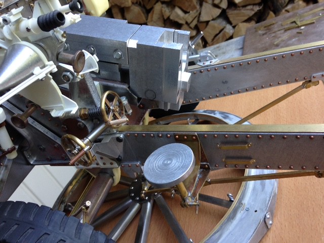
The gun slide also received a new gear quadrant (all welds still look what messy, forgot to clean them....):
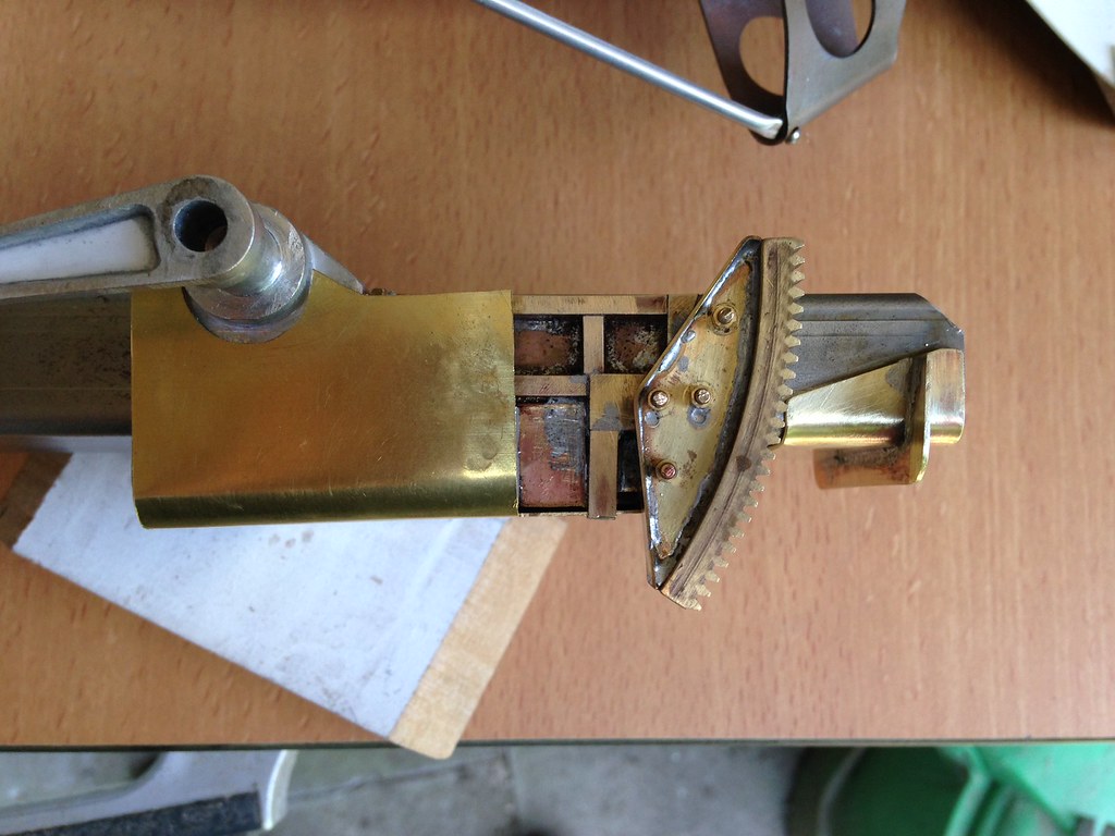
The quadrant was made from a mod.07 tooth rack bend in the right curve. This part was the most difficult to make and took some attempts to have it line up with the elevating cog. At the end of the slide the travel lock connection is fitted.
Also shown in the pic is the cradle reinforcement (brass shell, in-progress) that will envelop the cradle and the cradle hinge points.
Cheers,
Marcus
On the original everything is grouped into one casting that is connected with rivets to the cradle, as can be seen in the pics in my previous post.
What's to loose?
So I drilled a new hole to feed the elevating axle through, and replaced the kit parts EJO146 for a brass cog. The gear box was moved such that I could use one of its original boltholes and since the right bolt was now outside the cradle I used a mall locating pin instead. The kit yoke for the traversing arm was fitted where the new axle position is now and had to be re-positioned also ..... It was replaced with a new brass yoke and bolted onto the side of the cradle. The original holes were filled and sanded smooth.
The new cog and traversing yoke (parts are still in 'the rough' and need cleaning and polishing):
I also had to move the traversing wheel support on the carriage side (kit part EJO160). Though the kit part could have been used (only new locating holes are needed) I replaced the support by a new brass one.......
All parts fitted:,
The gear box will receive some 'massaging' with a file to let it resemble the original more but that is for later.
The gun slide also received a new gear quadrant (all welds still look what messy, forgot to clean them....):
The quadrant was made from a mod.07 tooth rack bend in the right curve. This part was the most difficult to make and took some attempts to have it line up with the elevating cog. At the end of the slide the travel lock connection is fitted.
Also shown in the pic is the cradle reinforcement (brass shell, in-progress) that will envelop the cradle and the cradle hinge points.
Cheers,
Marcus
-
Stephen White
- Site Admin
- Posts: 3099
- Joined: Sat Oct 11, 2008 7:05 pm
- Location: Dorset
- Has liked: 974 times
- Been liked: 2044 times
- Contact:
Re: Marcus's 25 pounder
Marcus, beautiful, detailed model engineering. This sort of post is a real inspiration. Thanks. Stephen
-
Marcus Kwa
- Posts: 176
- Joined: Wed Nov 13, 2013 6:22 pm
- Been liked: 39 times
Re: Marcus's 25 pounder
Hi Stephen,
Thanks for the comments!! I have watched your centurion build with pleasure and the weathering part as future inspiration, as there will be a time (in the far future....) this kit is 'finished' and all those brass details need to be covered by paint.......
By the way, how do you clean the brass parts after soldering?
Marcus
-
Robert E Morey

- Posts: 2252
- Joined: Wed Jul 18, 2007 12:59 am
- Location: Seattle, WA USA
- Has liked: 102 times
- Been liked: 698 times
Re: Marcus's 25 pounder
Marcus,
Beautiful work on the brass detail parts. They add a lot of realism to the model. My cleaning sequence for brass soldered parts for what its worth may be helpful:
1) Scotch-bright pads are helpful for removing soldering discoloration.
2) Clean parts in lacquer thinner or mineral spirit to remove flux.
3) Then a good scrub with toothbrush and soap (Dawn dishwashing soap is very good) to remove any remaining oils etc.
Its important to remove any flux as it is corrosive and will come through paint.
Best regards,
Bob
-
Robert Reid
- Posts: 578
- Joined: Mon Oct 09, 2017 9:49 pm
- Has liked: 96 times
- Been liked: 437 times
Re: Marcus's 25 pounder
Marcus:
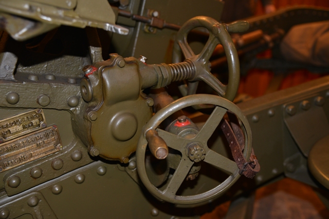
Very interesting photograph! I was not aware that the same Clinometer used on the Vickers... was used on the 25 Pdr.!
I restored one of these Clinometers to go with my two Vickers... one smooth brass jacket, one fluted jacket.
This one was a battlefield dug item that I had to restore... re-making all the steel screws! The rest of it cleaned up rather nicely. Amazingly, the bubble level was still intact! It took a great deal of care to clean up the glass level without breaking it! But the finished product was remarkable. It currently sits on my Vickers!

Some beautiful pictures in your build thread and definitely some ideas when it comes to doing mine! I have Dave Dibb's update kits and plan on some modifications of my own. And now I have to figure out how to make a 1/6th scale Clinometer!
Cheers,
RPR
Very interesting photograph! I was not aware that the same Clinometer used on the Vickers... was used on the 25 Pdr.!
I restored one of these Clinometers to go with my two Vickers... one smooth brass jacket, one fluted jacket.
This one was a battlefield dug item that I had to restore... re-making all the steel screws! The rest of it cleaned up rather nicely. Amazingly, the bubble level was still intact! It took a great deal of care to clean up the glass level without breaking it! But the finished product was remarkable. It currently sits on my Vickers!
Some beautiful pictures in your build thread and definitely some ideas when it comes to doing mine! I have Dave Dibb's update kits and plan on some modifications of my own. And now I have to figure out how to make a 1/6th scale Clinometer!
Cheers,
RPR