Marcus's 25 pounder

All topics related to Armortek's 25 Pdr
Marcus Kwa
Posts: 176
Joined: Wed Nov 13, 2013 6:22 pm
Been liked: 39 times

Re: Marcus's 25 pounder

Post by Marcus Kwa »

Hi Steve,
Bellows, that was the name I was looking for!
I have made it my mission in life to use things what they are not intended for...... and getting away with it!! :twisted:

Cheers,

Marcus

Bob Farmer
Posts: 34
Joined: Mon Mar 03, 2014 4:46 pm
Location: Moray, Scotland

Re: Marcus's 25 pounder

Post by Bob Farmer »

Hi Marcus

I really like the work you are doing to your 25 pdr, if mine comes out half as good I will be well pleased. Are there any updates yet?

What size are the rivets you replaced the kit ones with as I also think yours are closer to scale?

Keep up the good work

Bob

Marcus Kwa
Posts: 176
Joined: Wed Nov 13, 2013 6:22 pm
Been liked: 39 times

Re: Marcus's 25 pounder

Post by Marcus Kwa »

Hi Bob,
Sorry no updates, a bit busy with non modelling related projects....... :cry:
But I can answer your question on the rivets! I replaced them for 1/16" x 1/4" copper round head rivets. I bought them on ebay:
http://stores.ebay.nl/hootflipflopandfl ... 34.c0.m322

Be warned: since the heads are only a bit larger than the pre-drilled holes you need to center each and every one of them, or you will have a gap!! :roll: For the rivets requiring to fasten plates and fittings I shimmed the rivet with gluing leadfoil around the shank before gluing them in. The remainder of the rivets were glued using a gel type (gap filling) superglue. Not sure if I would do it again :? .......

Best regards,

Marcus

Bob Farmer
Posts: 34
Joined: Mon Mar 03, 2014 4:46 pm
Location: Moray, Scotland

Re: Marcus's 25 pounder

Post by Bob Farmer »

Thanks for the information. I think I will go to the effort as I like the look of the effect on yours.

Marcus Kwa
Posts: 176
Joined: Wed Nov 13, 2013 6:22 pm
Been liked: 39 times

Re: Marcus's 25 pounder

Post by Marcus Kwa »

A brave soul!! :D
In combination with the smaller rivets I also used smaller bolts and nuts, as to have no size difference between them especially on the gunshield (on the actual gun all gunshield fittings are riveted). Most of the gunshield fittings on my model were fastened with M2x5 bolts and nuts. I intend to fill the bolthead hex hole with some super glue before giving the gun its primer, then no difference should be visible (from the front that is....)!
When using Dave's update set: the cast-on rivets are easily removed with a sprue cutter (or side cutter).

Enjoy!!

Marcus

Dave Backway
Posts: 103
Joined: Mon Oct 06, 2014 6:27 pm
Location: Exeter, Devon
Has liked: 12 times
Been liked: 55 times

Re: Marcus's 25 pounder

Post by Dave Backway »

Hello Marcus,

I have just bought 25pdr kit and was amazed at the detail supplied and I have been reading the build logs on the forum. I was very interested in your build and the use of smaller rivets and other fittings. I was wondering how you have got on with your build since your last post and whether you have any further details or pictures to post.

I'm currently in the research phase and as the kit is a Christmas present to myself from my family, I have plenty of time to obtain knowledge and plan the build before I should be able to start it.

Regards

Dave

Marcus Kwa
Posts: 176
Joined: Wed Nov 13, 2013 6:22 pm
Been liked: 39 times

Re: Marcus's 25 pounder

Post by Marcus Kwa »

Hello Dave,
No more progress but I will pick up the build soon! Finally have some more spare time (I hope.....).
Also I have to because the steel parts are starting to rust! So nest step will to undercoat most of the piece, after all most of the detailing is done. Last part I was working on was the panoramic (or dial) sight.

Best regards,

Marcus

Marcus Kwa
Posts: 176
Joined: Wed Nov 13, 2013 6:22 pm
Been liked: 39 times

Re: Marcus's 25 pounder

Post by Marcus Kwa »

It has been a while since I last reported the progress on my 25 pdr. build!
The steel has rusted and the rest of the model was covered in a thick layer of dust....... :oops: Nothing that can't be dealt with!

Last progress reported was some initial work on the sight and gun laying systems. The dial or panoramic sight (sight on the small turntable, peeping over the collapsed gunshield) is now finished. Also the ruler on the ranging cone has been fitted as are the iron sights on the telescope brackets. Last, in the right lower corner, the elevation indicator.
Image

Another shot showing the iron sights, dial sight and the modified fork on the linkage arm. The part connected to the sight system has a slight curve:
Image

From a different angle, at the bottom of the 'half moon' the clinometer is visible:
Image

Other areas of progress were merely the addition of small fittings like the brackets for the ranging poles to the front of the gun shield:
Image

Image

The brackets for the traversing platform levers were filed down to show the top and bottom ribs (next will some file work on the handles of the levers after I have the strength back in my hands after the previous filing session...... :wink: )and Dave's traversing poles were fitted together with their brackets :
Image

I am currently finishing the brake system for the wheels and started unpacking the limber! Keep you all posted!
Oh yes, and I will have a surprise for all those tiger owners :twisted: . It is nearing completion and has the codename 'Pheasant'.......

Cheers,

Marcus

Ian Rodney
Posts: 480
Joined: Thu Jul 05, 2012 6:39 am
Been liked: 53 times

Re: Marcus's 25 pounder

Post by Ian Rodney »

Looking Great Marcus

You've done a lot of good work on your 25 pdr…….just wait until you get started on your Limber kit!
It's fun to build, believe you me……!

Cheers
Ian

Marcus Kwa
Posts: 176
Joined: Wed Nov 13, 2013 6:22 pm
Been liked: 39 times

Re: Marcus's 25 pounder

Post by Marcus Kwa »

Hi Ian,
I just love this kit! If the limber is half the fun that would be more than oke!
Following your limber build closely! Did you consider making the leaf springs for the door stoppers by laminating strips of brass or steel? I think i will try soldering a bunch together tommorrow.

Cheers

Marcus

Ian Rodney
Posts: 480
Joined: Thu Jul 05, 2012 6:39 am
Been liked: 53 times

Re: Marcus's 25 pounder

Post by Ian Rodney »

Hi Marcus,

Yes I believe the 25 pdr kit will be fun to build once I have finished working on my own Limber kit.

The limber is quite straight forward if one does not get sidestepped like me by getting caught up with lot's of details! it all depends on how far you want to take it too!
I have been held up by taking a long time over my Tow Bar Eye, with making moveable working parts, like the handle and housing with springs etc.
Have just finished making all the parts now for the Tow Bar Eye end once I have changed a few details on my technical drawings I will be back to download some final pics and illustrations on the Tow Bar to share on the Forum.

No I have not considered yet making the leaf springs for the door stoppers, but would be interesting to see what you have come up with!

Cheers
Ian

Ian Rodney
Posts: 480
Joined: Thu Jul 05, 2012 6:39 am
Been liked: 53 times

Re: Marcus's 25 pounder

Post by Ian Rodney »

Hi Marcus,

While I was getting carried away with Limber build and techie drawings, I forgot to ask you how you got on with making your leaf springs door stoppers that you said you would have a go at!

Any pics of your efforts on above would be appreciated for sure!

Cheers
Ian

Marcus Kwa
Posts: 176
Joined: Wed Nov 13, 2013 6:22 pm
Been liked: 39 times

Re: Marcus's 25 pounder

Post by Marcus Kwa »

Speaking of the Devil! Since it is raining outside I took out my soldering tools.
Cutting the 6mm wide brass strips is quite straightforward. The longest one with the fixture for the bar was bend using the kit part as template. Next was the sanding of the overlap areas to provide a good grip of the solder. The leafs were then bundled with a vice and heated with a torch, a tiny bit of solder, the result:

Image
Image

However when I was finished soldering the first 2 springs sets I noticed on photos of the real limber that the ends of the individual leafs are tapered ........ :oops:

Also the brass strips seam to have moved in the vice during heating. For the next two springs I will drill a hole in the overlap section (clamp area) and insert a rivet before soldering. The rivet will fit inside the hole on the securing plate of the clamp of the limber as on the original. Keep you posted!

Ian Rodney
Posts: 480
Joined: Thu Jul 05, 2012 6:39 am
Been liked: 53 times

Re: Marcus's 25 pounder

Post by Ian Rodney »

Thanks Marcus,

For posting these good images of the leaf springs, and clamps for your limber.

Speaking of the Devil here too, while I pop in and out of my own garden trying to get things done outdoors.
Back inside again to get on with my techie limber drawings.

Will save these images and any more you post on the forum onto my "things to do list"

Looks fairly straight forward, he says?

Cheers
Ian

Marcus Kwa
Posts: 176
Joined: Wed Nov 13, 2013 6:22 pm
Been liked: 39 times

Re: Marcus's 25 pounder

Post by Marcus Kwa »

Hi all,
Just finished some mod's to the gun shield. Actually I only intended to take the gun shield off, remove the rust and refit the shield to the gun..... I got carried away....

The major mod's were the replacement of the 2nd and 4th hinge of the gun shield top. The 2 hinges have a different shape on the actual gun and incorporate the locking mechanism for the gun shield top in both folded down and extended positions. More on these hinges later!

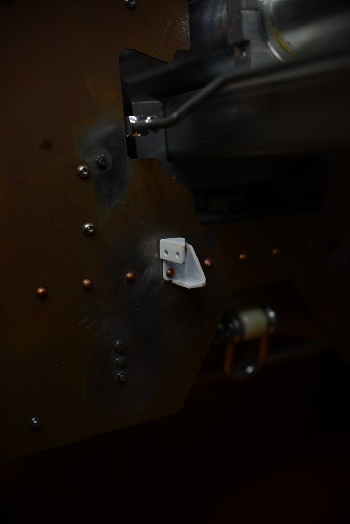
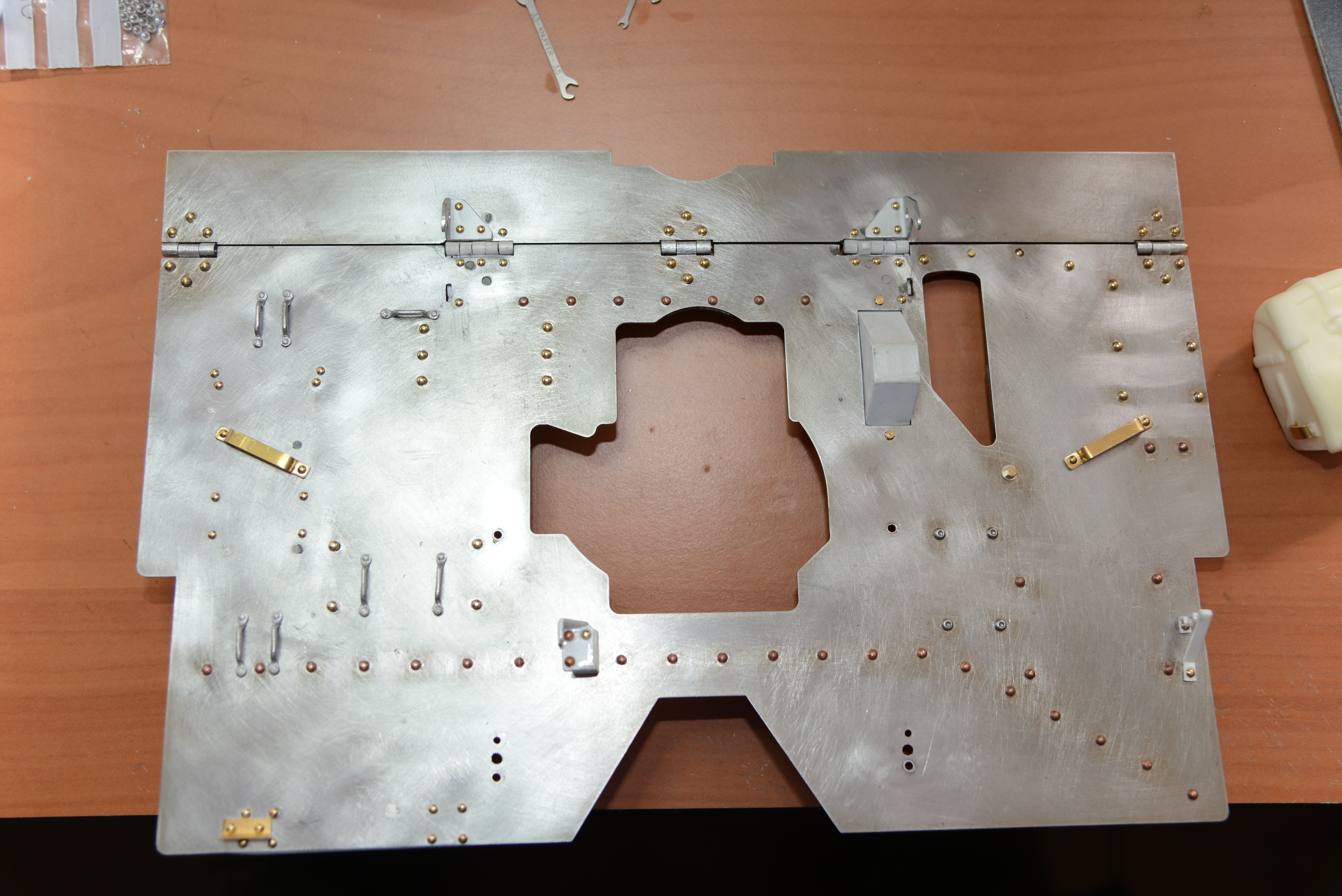
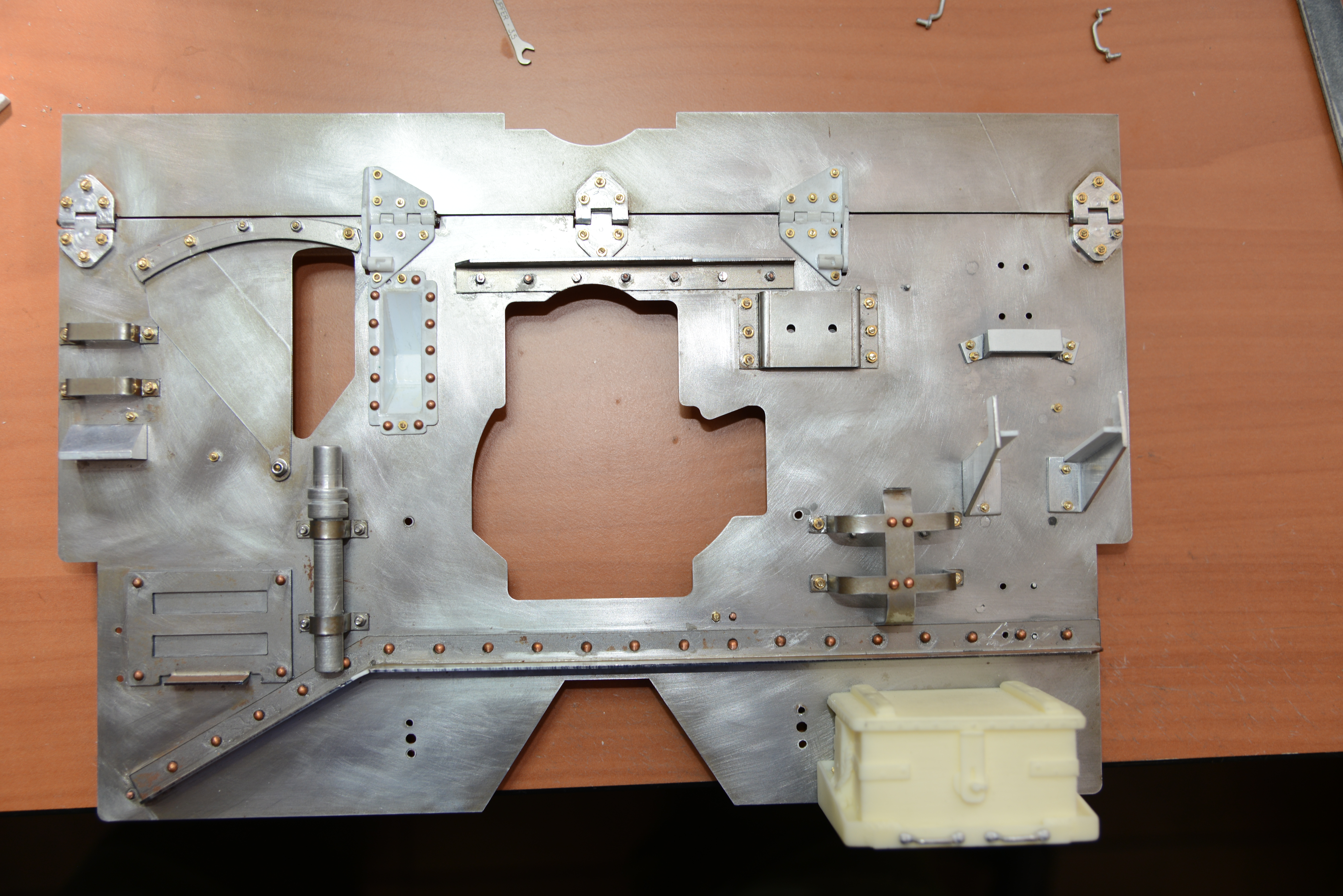
To the front of the shield 2 large handles were fitted, made of brass strip 4mm wide 0.6mm thick. In the lower left corner the stopper for the spade was added fitting neatly between the rivet clusters holding Dave's spares box to the gun shield. The stopper is a brass angle line 5.0x5.0x0.6mm.
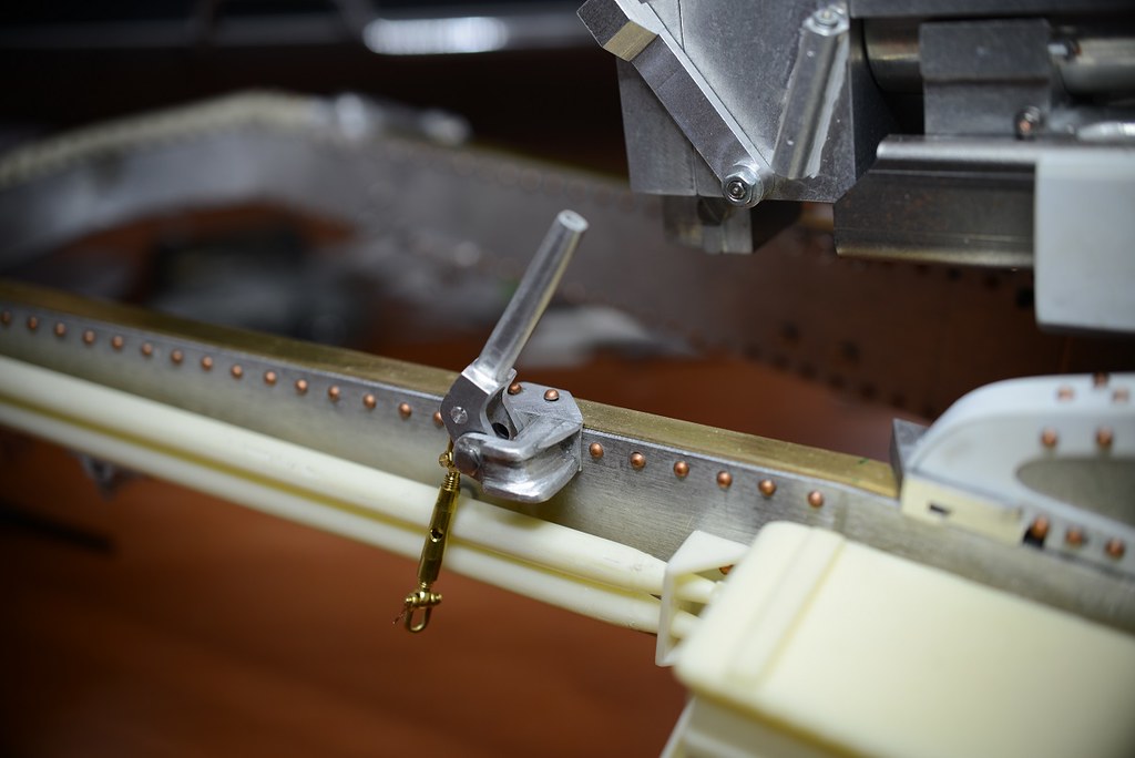
Finishing touch are the tie-downs (Armorpax) for the spade and towing rope. For most of these fittings new holes were drilled in the gunshield. The original holes that were not used were soldered shut.
Image

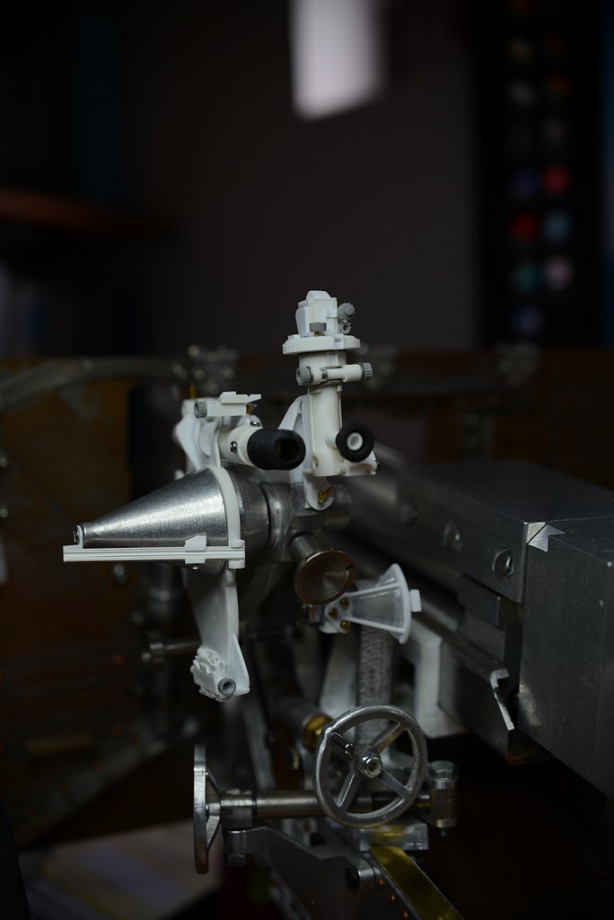
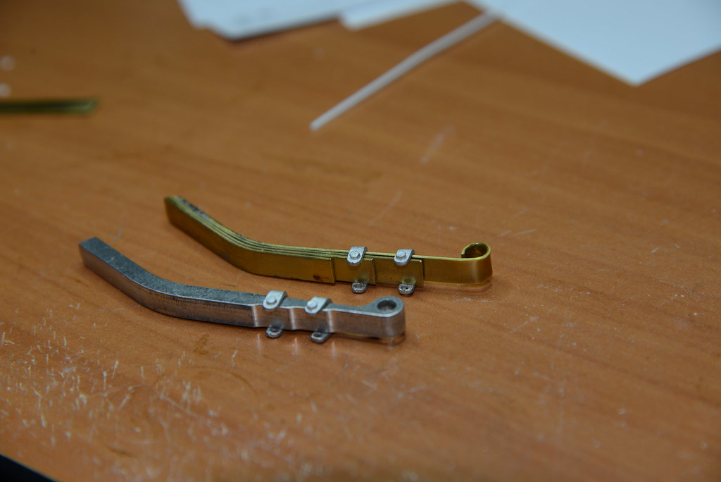
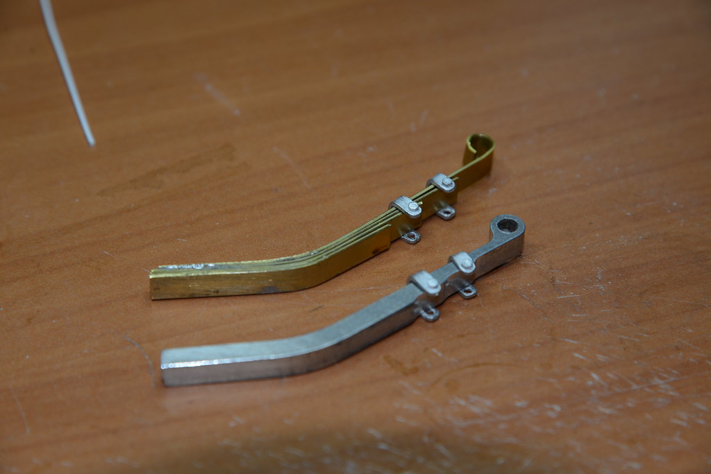
The two hooks just above the new hinges are the retaining hooks for the gun shield in the folded position and are part of the new hinge assembly. The hooks are cut and filed to shape from an aluminium angle line 1.0mm thick:
Image

When folded down the tips of the hooks pass through slots in the gun shield so the locking bolt at the back of the gun shield can be engaged:
Image

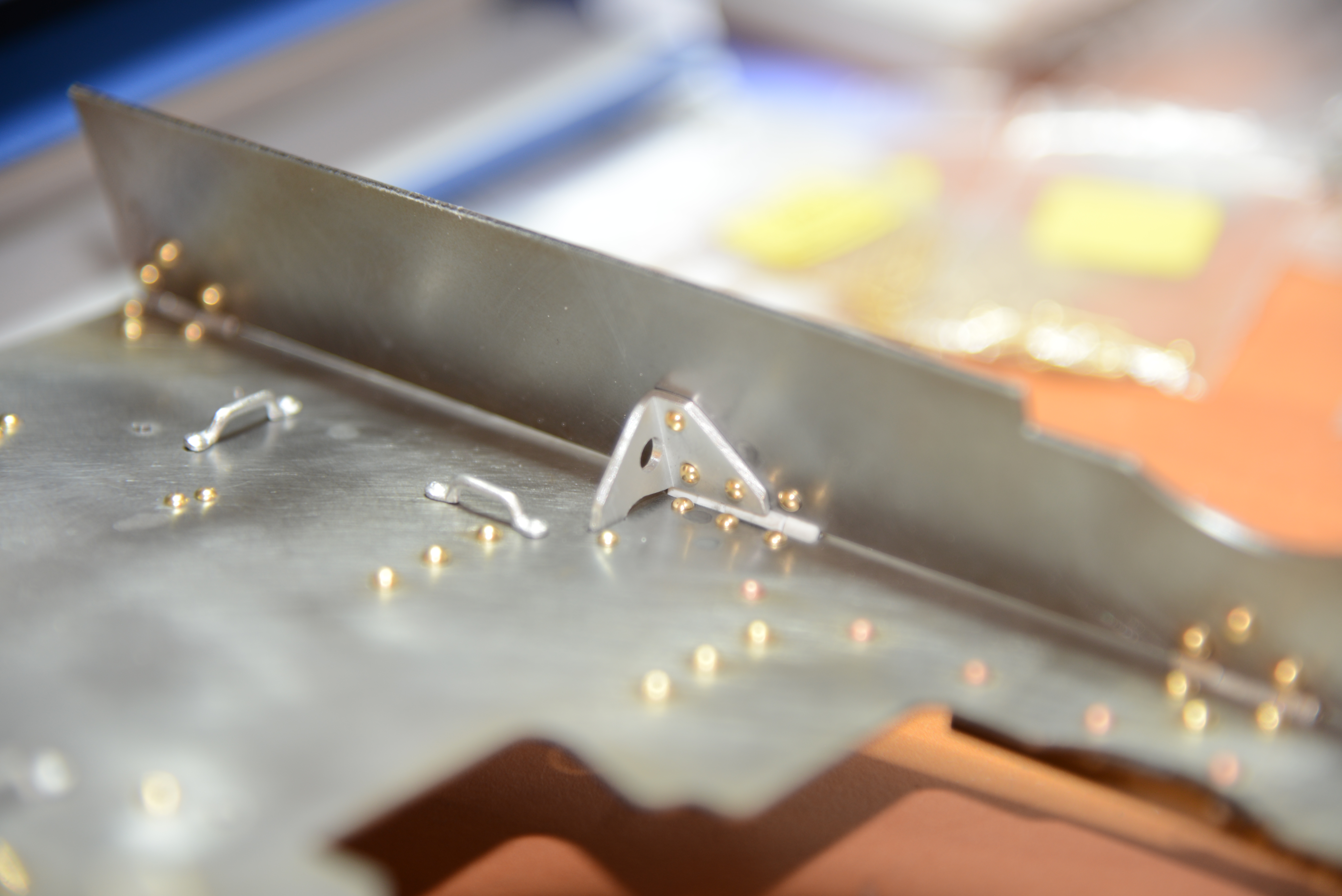
Looking at the back of the shield the tip of the hook is visible (actual locking bolt is missing in the photograph). Also visible is the locking arm for the gunshield in the extended position:
Image

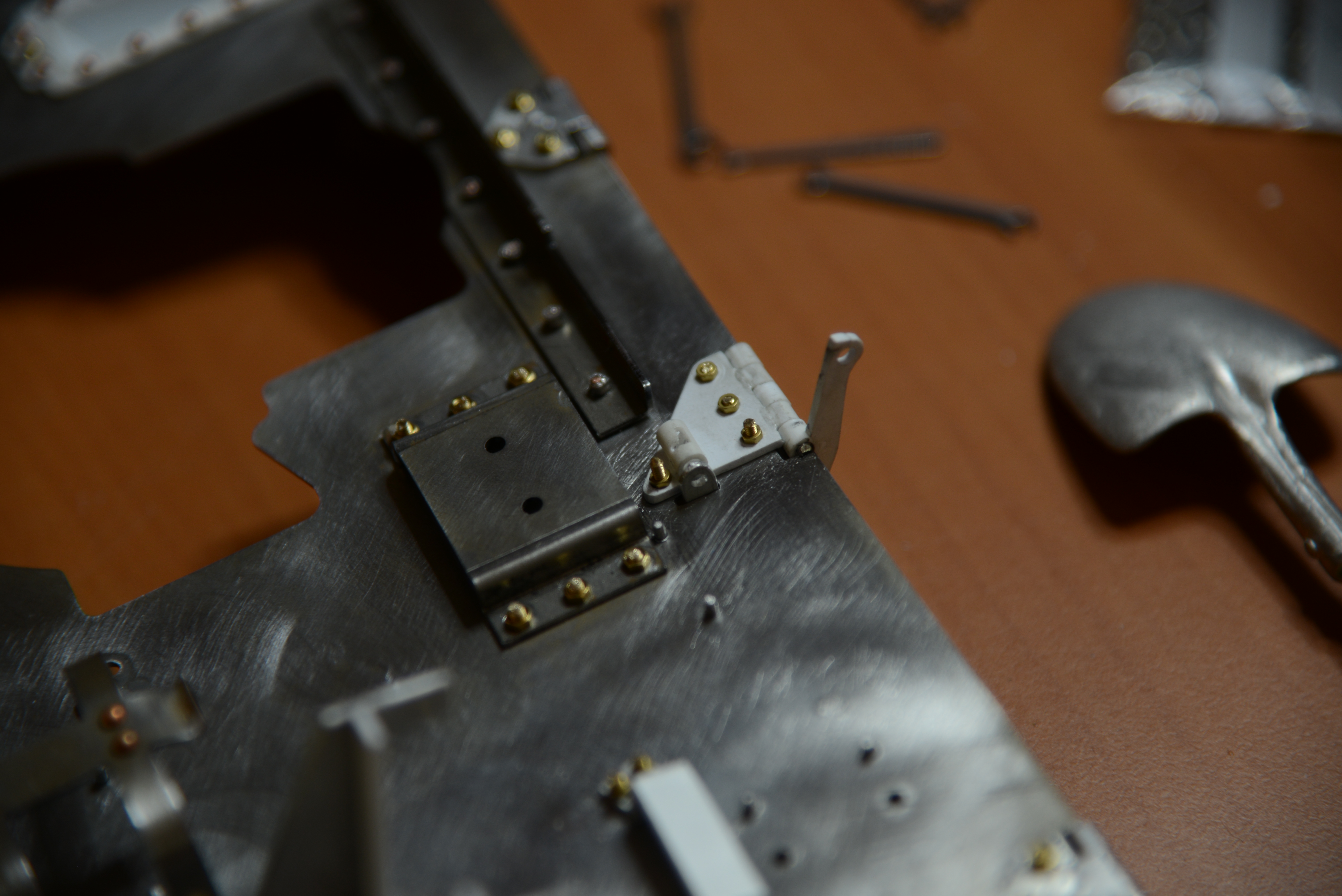
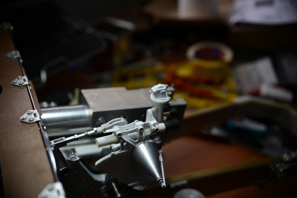
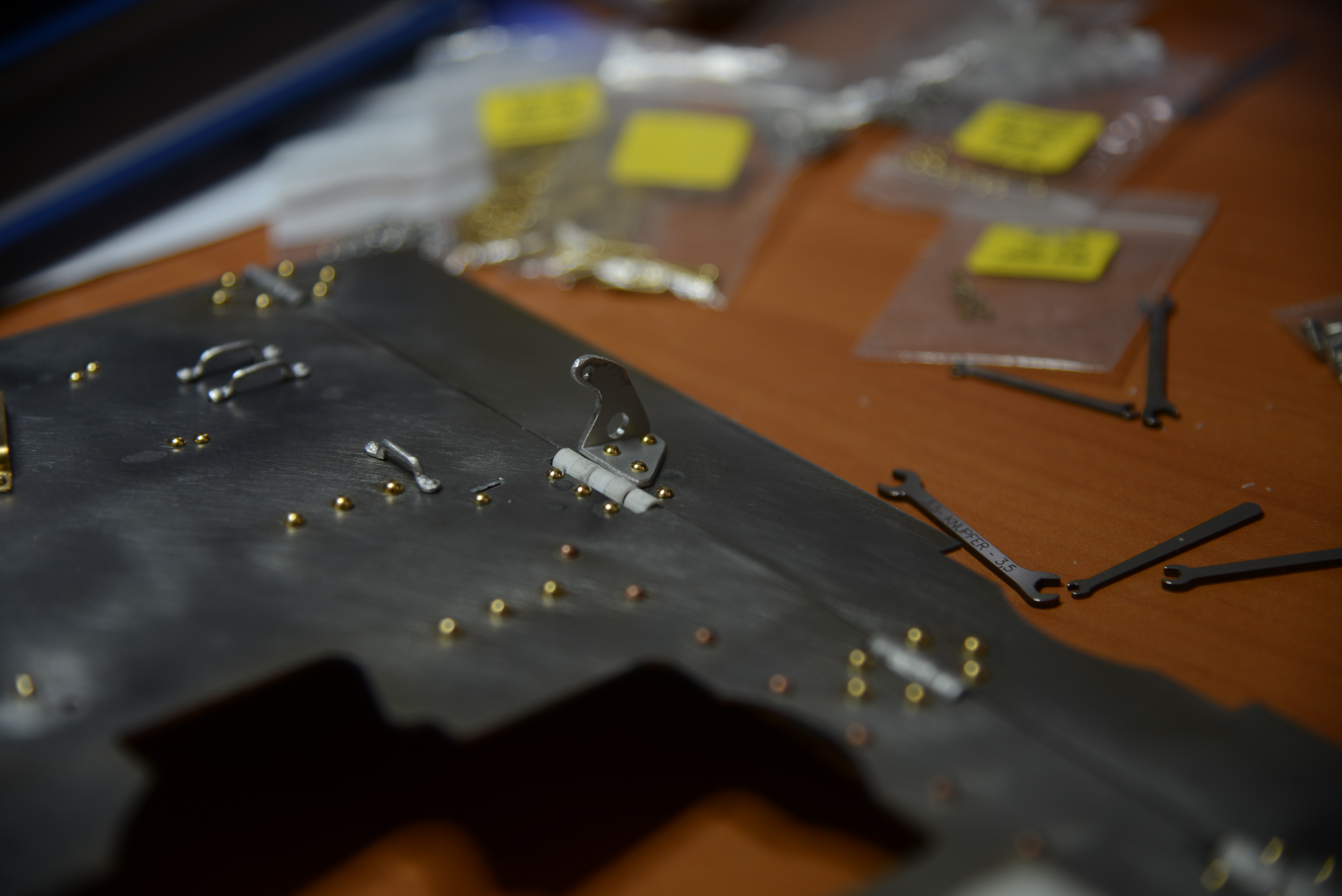
Now we are at the back of the shield let's look at the mod's here! Clearly visible are the new hinges and their distinctive shape. The hinges are in styrene but I am trying to make them from brass or aluminium since they are quite fragile.
Image

I replaced the kit's one-piece sight carrying pouch/bag bracket EJ0237 with 2 separate brackets fitted with 2 bolts/rivets each. The whole bracket assembly was also moved a bit upwards. The position of these brackets differ slightly on the actual pieces I have examined, I just chose the position of an example in the collection of the 'Artillerie Museum'. I also replaced the upper bracket for the typically inclined bracket fastened by 4 rivets. All brackets were made (sawed and filed) from aluminium angle lines 1.5mm thick.

All gun shield fittings were fastened by brass roundhead rivets with a threaded shank (M2 and M1.6). I still have to trim them flush with their retaining nuts.

That's it for now! The work on the brake system has been delayed by these gun shield mod's but is next (promise....!!)

Cheers,
Marcus

Post Reply