How to:
Posted: Mon Dec 12, 2011 3:33 pm
Fit a Benedini Encoder to a Futaba 10CAP transmitter.
The second in an occasional series of tutorials.
With the help and soldering skills of Marcel, I have put together a short tutorial on fitting a Benedini Encoder to a Futaba 10CAP transmitter.
Modern electronics are sensitive to electrostatic discharge, so keep handling of the internal boards to a minimum.
It may feel like I am stating the obvious, but THIS MODIFICATION WILL INVALIDATE ANY WARRANTY YOU MAY HAVE!
You will need a good quality soldering iron, and a de-soldering tool is very useful. Available from RS, Maplin, Ebay, etc, etc.
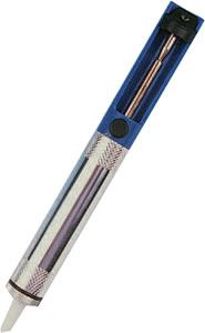
A Solder Sucker
The Futaba 10CAP transmitter is incredibly flexible, with 8 of the channels being proportional, and assignable to any knob, switch or slider.
It was decided to use the right hand slider control as the control to be replaced. As you can see from the picture of the internal layout, the 3 knobs on the front face are difficult to get to, and there is very little room for the encoder. Positioning of the Benedini Encoder knob and switch are personal preference.

1/ Remove the slider of its control and unmount the control. Keep the mount, as this will be used later.

2/ De-solder the slider control from the circuit board, making sure the holes are clear of solder.

3/ Solder the three wires from the encoder onto the board, making sure that the RED wire is in the centre hole. The brown and orange wire can go in either position.

3/ Mount the rotary switch in the required position, ensuring the wires and circuit board are clear of the moving controls. In this case the rotary switch was mounted on the top of the transmitter, with the toggle switch mounted on the removed slider mount.

4/ Once reassembled, access the AUX CH menu as per page 46 of the manual and assign 1 of the auxiliary channels to VrE. This is the channel you will be using to control the sound board. Access the END POINT menu as per page 39 of the manual and set the end points of your chosen channel to 140/140. This will give you the maximum separation between sound selections. If you leave it at 100/100 you can sometimes select the incorrect sound. Power up your radio system with a servo connected to your chosen channel. Rotate the knob to each position and operate the toggle switch. The servo should move through its full sweep in 12 separate steps. You now need to connect to the sound board, set it to encoder control and assign each position to a different sound.
Thanks to Marcel for doing the hard work. The transmitter is going to be used on Eddie de Ruyter's fantastic scratch built Panzerhaubitze 2000, which can be seen at http://www.armortek.co.uk/Forum3b/viewt ... f=2&t=3222 Look forward to seeing some video of it running.
Hope this helps
Cheers
Mick
P.S. If anyone is interested in any other systems or radios, I'll consider adding more "How to" posts.
The second in an occasional series of tutorials.
With the help and soldering skills of Marcel, I have put together a short tutorial on fitting a Benedini Encoder to a Futaba 10CAP transmitter.
Modern electronics are sensitive to electrostatic discharge, so keep handling of the internal boards to a minimum.
It may feel like I am stating the obvious, but THIS MODIFICATION WILL INVALIDATE ANY WARRANTY YOU MAY HAVE!
You will need a good quality soldering iron, and a de-soldering tool is very useful. Available from RS, Maplin, Ebay, etc, etc.
A Solder Sucker
The Futaba 10CAP transmitter is incredibly flexible, with 8 of the channels being proportional, and assignable to any knob, switch or slider.
It was decided to use the right hand slider control as the control to be replaced. As you can see from the picture of the internal layout, the 3 knobs on the front face are difficult to get to, and there is very little room for the encoder. Positioning of the Benedini Encoder knob and switch are personal preference.
1/ Remove the slider of its control and unmount the control. Keep the mount, as this will be used later.
2/ De-solder the slider control from the circuit board, making sure the holes are clear of solder.
3/ Solder the three wires from the encoder onto the board, making sure that the RED wire is in the centre hole. The brown and orange wire can go in either position.
3/ Mount the rotary switch in the required position, ensuring the wires and circuit board are clear of the moving controls. In this case the rotary switch was mounted on the top of the transmitter, with the toggle switch mounted on the removed slider mount.
4/ Once reassembled, access the AUX CH menu as per page 46 of the manual and assign 1 of the auxiliary channels to VrE. This is the channel you will be using to control the sound board. Access the END POINT menu as per page 39 of the manual and set the end points of your chosen channel to 140/140. This will give you the maximum separation between sound selections. If you leave it at 100/100 you can sometimes select the incorrect sound. Power up your radio system with a servo connected to your chosen channel. Rotate the knob to each position and operate the toggle switch. The servo should move through its full sweep in 12 separate steps. You now need to connect to the sound board, set it to encoder control and assign each position to a different sound.
Thanks to Marcel for doing the hard work. The transmitter is going to be used on Eddie de Ruyter's fantastic scratch built Panzerhaubitze 2000, which can be seen at http://www.armortek.co.uk/Forum3b/viewt ... f=2&t=3222 Look forward to seeing some video of it running.
Hope this helps
Cheers
Mick
P.S. If anyone is interested in any other systems or radios, I'll consider adding more "How to" posts.