Bovington Tiger 1 Photos - Engine Deck
Posted: Sun Nov 07, 2010 11:11 pm
Last week I visited the Bovington Tank Museum and took plenty of pictures of the Tiger 1, which I’ll post on the forum. I’m currently detailing the engine deck of my Mid Production (021), and so I was keen to take plenty of pictures and check out the level of the engine covers in relation to the air vents. Unfortunately, the entire engine deck has been removed, along with the engine, fans, radiators and petrol tanks. The exhaust system has also removed. After talking to the staff it appears the engine is going to be rebuilt and the other parts repaired and serviced, which may mean the Tiger is going to be out of commission for some time.
Although the engine deck had been removed, I did manage to locate the front and rear vent covers tucked against the wall of the museum. The museum staff very kindly allowed me access to a storage area where the engine covers and other parts are being stored. So although I didn’t get to see all the parts fitted to the tank, I still got some very useful pictures before by camera battery finally died on me.
These first sets of pictures are of the engine deck parts. I hope you find these useful.
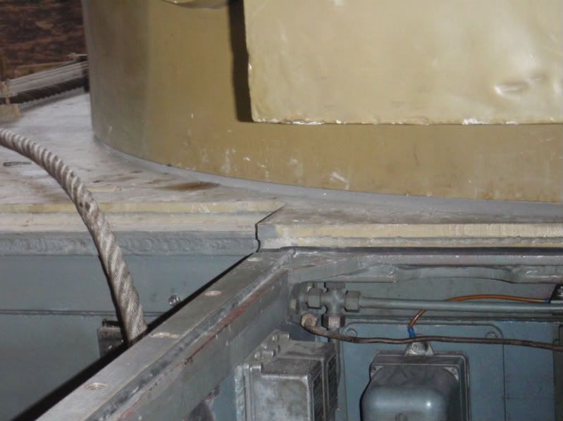
Here’s the exposed engine compartment which allows you to see how the outlet vents and engine cover meet up with the front deck.
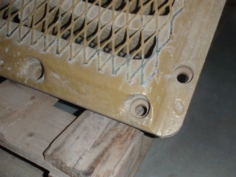
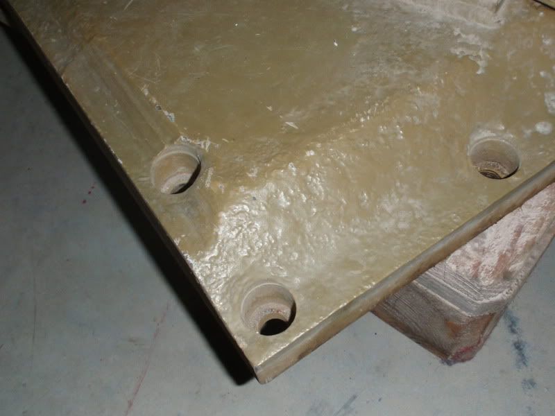
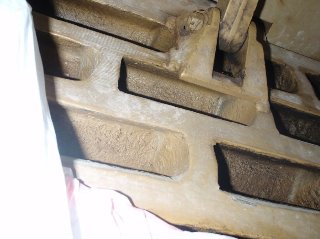
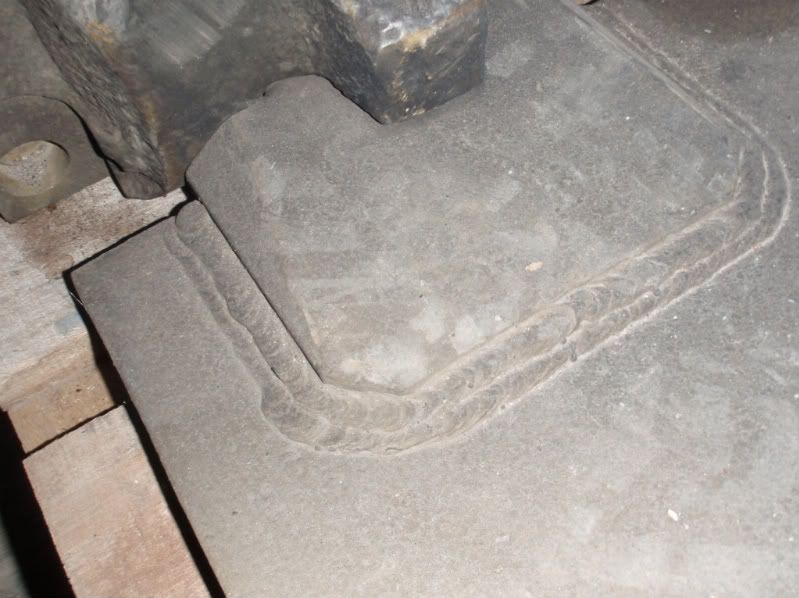
Here’s the outlet air vent covers, which shows a close up of the welds around the fuel caps, the rough cast finish to the cover and the recessed bolt holes.
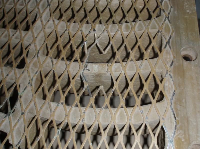
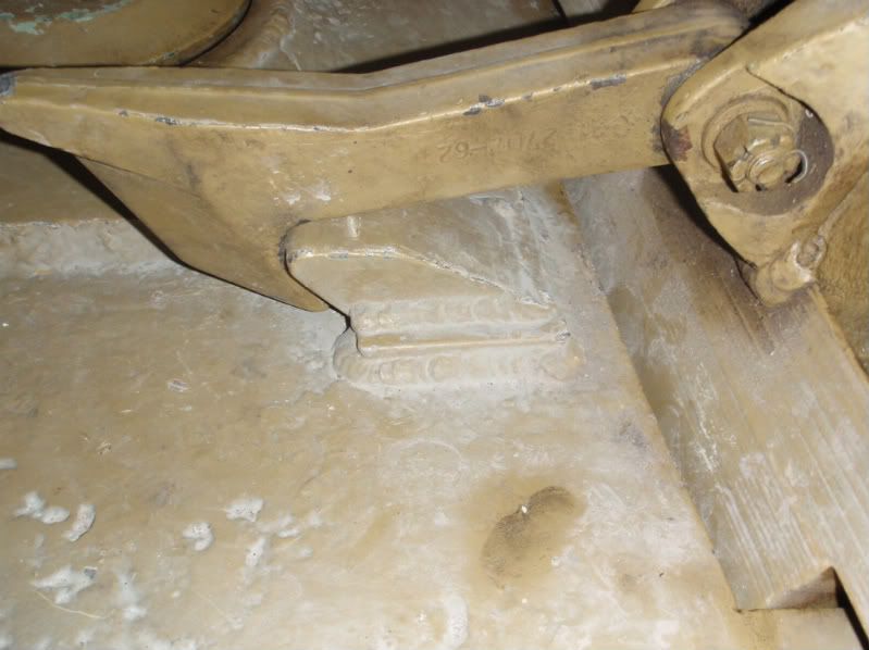
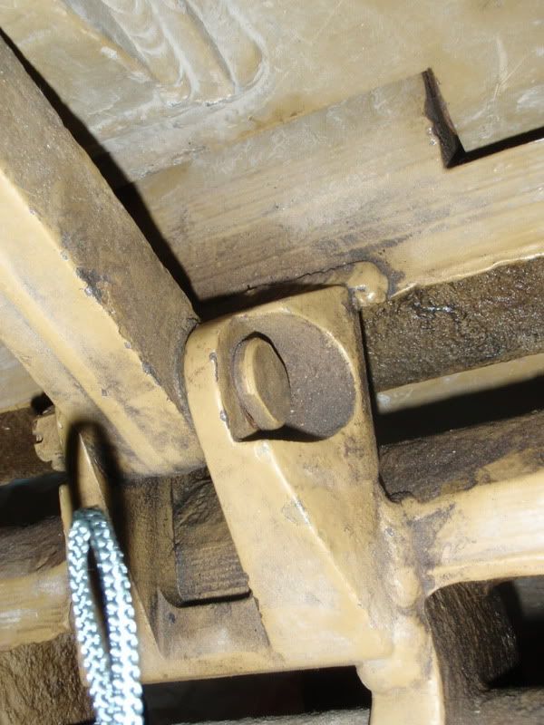
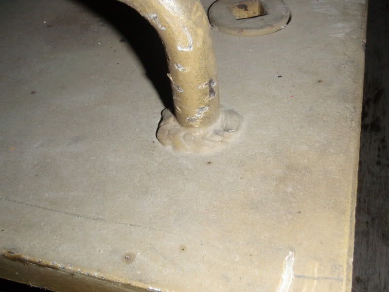
This is the air intake covers, which is still hinged to the radiator covers. We can see various shots of the hatch hook and its cast base, including the securing bolt; a threaded pin with a round flat head that has 2 flats for a spanner, and tightened with a castellated nut. We can also see all the welds on the various fittings. Again, you can see the rough cast finish to the cover and the recessed bolt holes. Note the shapes of the vents are quite complex and not the same as the Armortek vents. I would guess it would be very expensive to cast these and too time consuming to rework the kit vents.

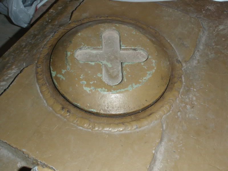
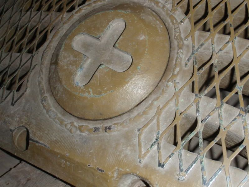
Here’s the round air filter cover and cap.
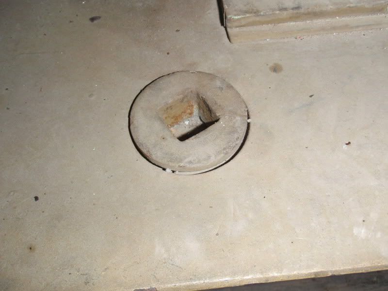
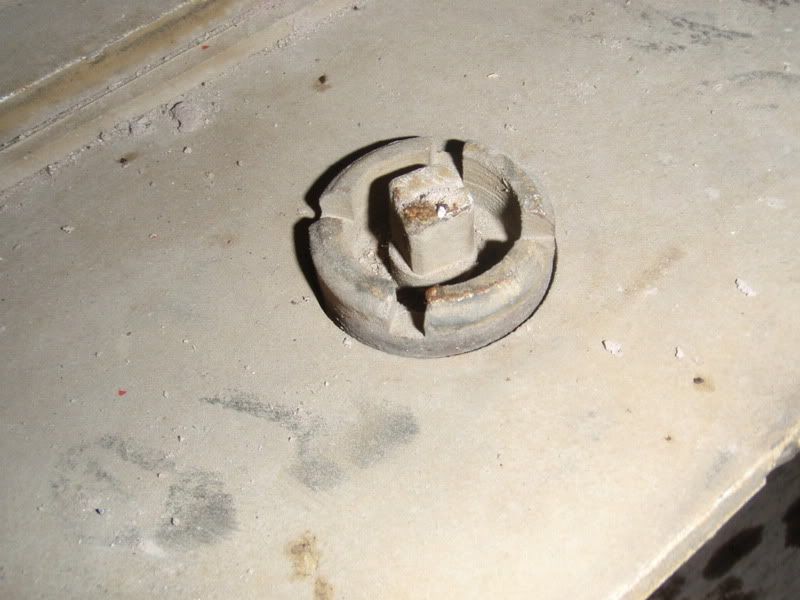
Here’s the square drive bolts for securing the engine cover and the watertight securing bolts that are made from 2 parts; a slotted head with a threaded bolt running through the centre with a square male head. You can also see the welds around the handles.
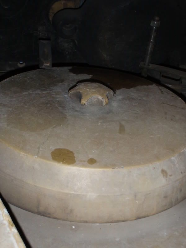
Here’s the round access cover to the engine, which has a cast finish.

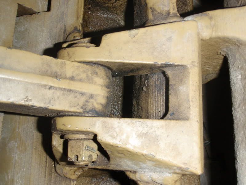
Here you can see the engine cover hinges which are squatter in shape than the kit parts, with a chamfered edge. You can also see the double weld lines.
Although the engine deck had been removed, I did manage to locate the front and rear vent covers tucked against the wall of the museum. The museum staff very kindly allowed me access to a storage area where the engine covers and other parts are being stored. So although I didn’t get to see all the parts fitted to the tank, I still got some very useful pictures before by camera battery finally died on me.
These first sets of pictures are of the engine deck parts. I hope you find these useful.
Here’s the exposed engine compartment which allows you to see how the outlet vents and engine cover meet up with the front deck.
Here’s the outlet air vent covers, which shows a close up of the welds around the fuel caps, the rough cast finish to the cover and the recessed bolt holes.
This is the air intake covers, which is still hinged to the radiator covers. We can see various shots of the hatch hook and its cast base, including the securing bolt; a threaded pin with a round flat head that has 2 flats for a spanner, and tightened with a castellated nut. We can also see all the welds on the various fittings. Again, you can see the rough cast finish to the cover and the recessed bolt holes. Note the shapes of the vents are quite complex and not the same as the Armortek vents. I would guess it would be very expensive to cast these and too time consuming to rework the kit vents.
Here’s the round air filter cover and cap.
Here’s the square drive bolts for securing the engine cover and the watertight securing bolts that are made from 2 parts; a slotted head with a threaded bolt running through the centre with a square male head. You can also see the welds around the handles.
Here’s the round access cover to the engine, which has a cast finish.
Here you can see the engine cover hinges which are squatter in shape than the kit parts, with a chamfered edge. You can also see the double weld lines.


