Late Production Tiger Project

Forum for discussion relating to Tiger 1, Mid, Early, Late Production and Sturmtiger
Post Reply
Steve Norris
Posts: 1225
Joined: Thu Jul 12, 2007 11:42 am
Location: Manchester
Has liked: 8 times
Been liked: 688 times

Post by Steve Norris »

Tim,
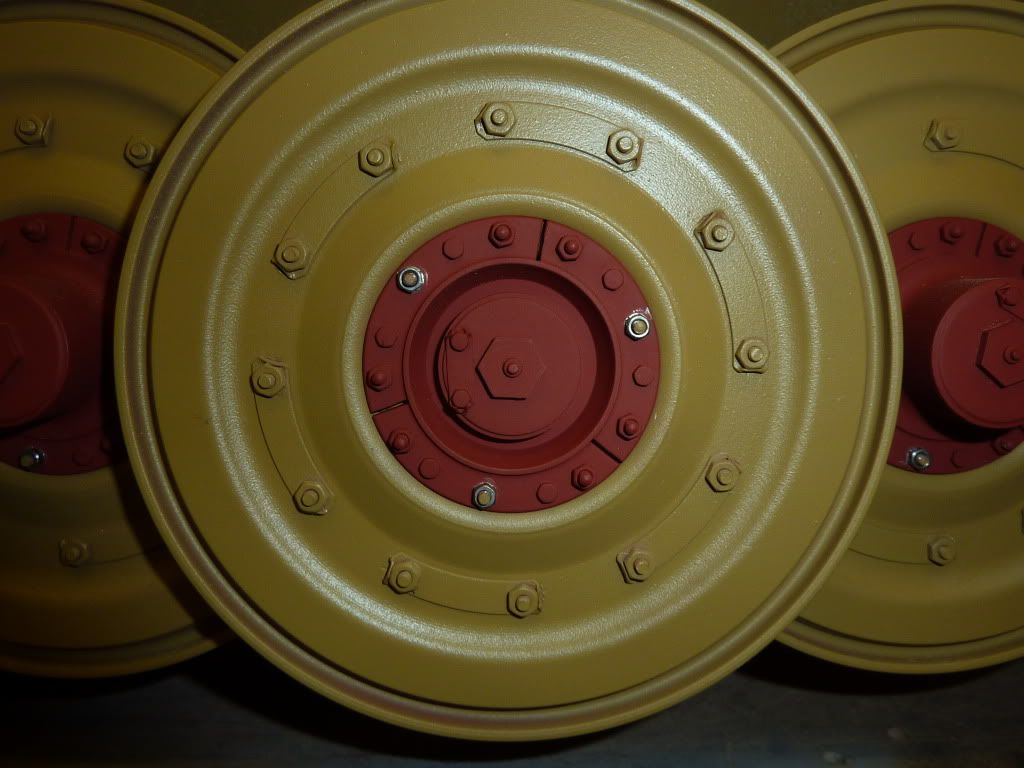
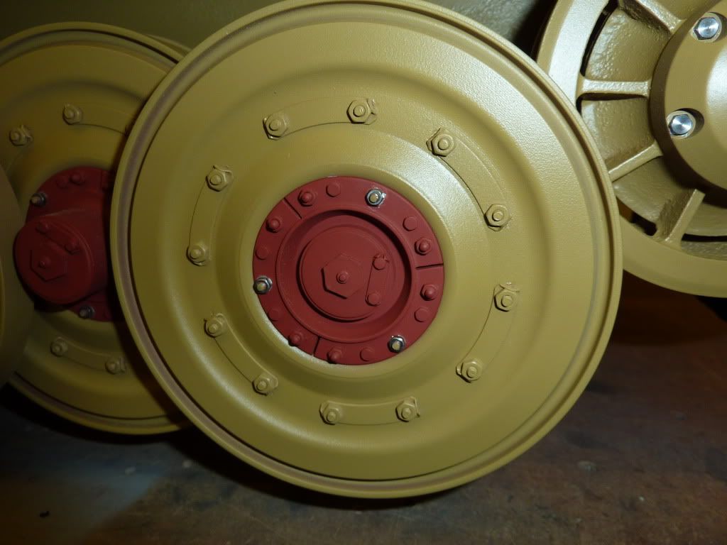
The Tigers comming along great, Glad you have found my wheel mod of use, heres some shots of my wheels as they are at the moment.

Image

Image

Image

The bump stops are going to be superb, are you planning on producing these parts for sale ?

All the best
Steve

simon_manning
Posts: 2024
Joined: Fri Nov 02, 2007 8:51 pm
Location: new forest,hampshire,u.k.
Been liked: 1633 times

Post by simon_manning »

there are some cracking posts and photos on this tiger thread,keep em coming! great detail.
simon manning.

User avatar
Adrian Harris
Posts: 5060
Joined: Thu Jul 12, 2007 10:46 pm
Location: Berkshire (UK)
Has liked: 1369 times
Been liked: 1567 times

Post by Adrian Harris »

Loving these construction shots, especially all the detailing being added.

I may have to get myself a Late Tiger when the next batch is available :lol:

Adrian.

Tim Bowman
Posts: 1762
Joined: Fri Jul 13, 2007 4:53 am
Location: Northern California
Been liked: 177 times
Contact:

Post by Tim Bowman »

Hi Bob

I will be making 4 masters to mold and will attempt to cast some in metal.

Hi Steve

Your Tiger looks GREAT!. I cannot answer the bump stop question until I successfully cast a set in metal. If I can do that, I will certainly make them available. Should have first 3D parts by Friday. Will post some photos after I have detailed them.

Onto hub caps in the mean time.

Happy tank building
Tim
"So long as one isn't carrying one's head under one's arm, things aren't too bad." – Erwin Rommel

Mike Cooper
Posts: 26
Joined: Thu Aug 16, 2007 2:27 pm
Location: Cleveland, UK

Post by Mike Cooper »

Hi Tim,

Can you tell me how you produced the profile of the pannier undersides/support brackets. I'm trying to detail out the same thing but can't find any details of the profile. How did you make yours ?

regards,
Mike

Tim Bowman
Posts: 1762
Joined: Fri Jul 13, 2007 4:53 am
Location: Northern California
Been liked: 177 times
Contact:

Post by Tim Bowman »

Hi Mike

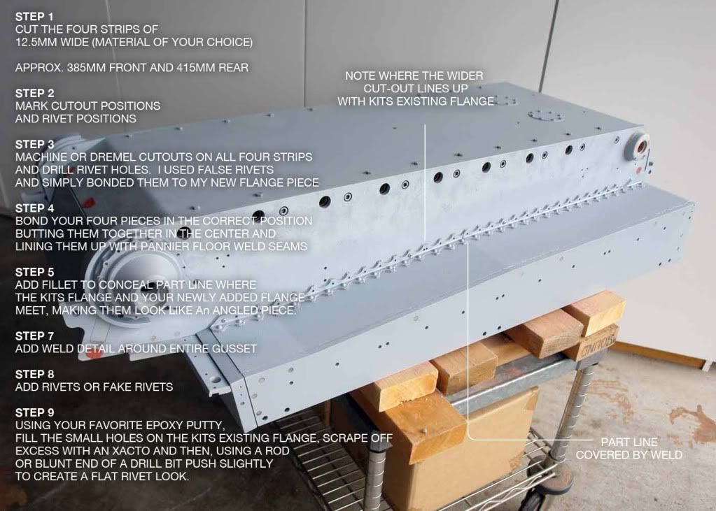
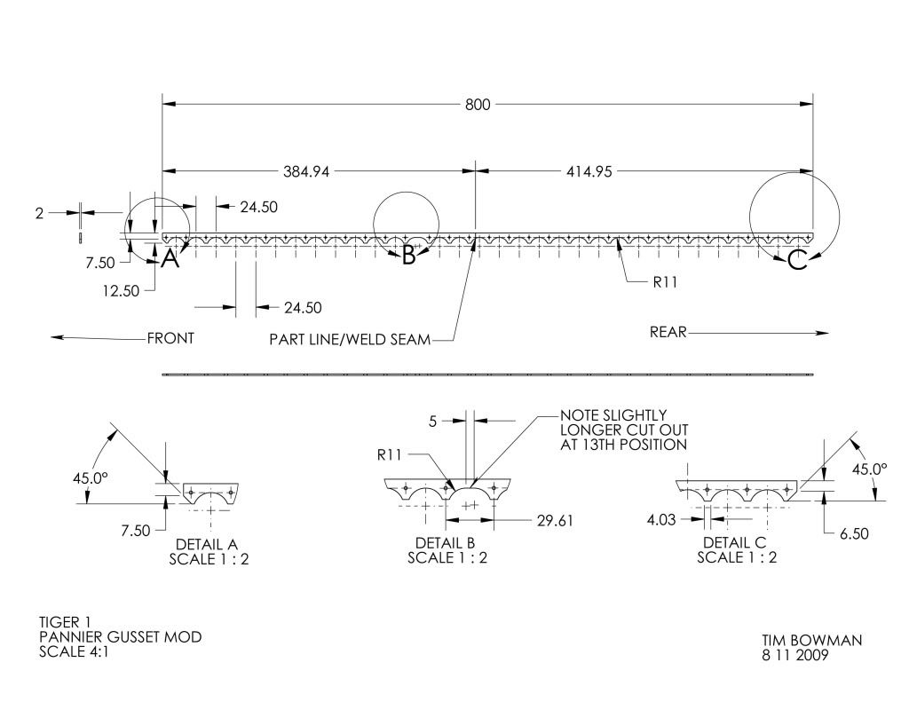
Here's a quick attempt to explain how I added the top side of the pannier flange on the late Tiger kit and a drawing I did of the parts. Left and right are simply mirrored. The drawing represents the right side pannier looking from the bottom of the tank.

Image

Here's the drawing I created off of the parts I made which was based off reference photos(right side of this drawing is the rear). Accuracy disclaimer: This is not meant to be a 100% accurate drawing of the real thing, just my best attempt. Please double check measurements on your own Tiger’s panniers for overall length.


Image

The small holes were not yet filled in the above photo. you can see how look filled on the previous page.

Hope this is helpful
regards
Tim
"So long as one isn't carrying one's head under one's arm, things aren't too bad." – Erwin Rommel

Dale jordan
Posts: 1428
Joined: Fri Jul 13, 2007 1:10 am
Location: Port Macquarie Australia
Been liked: 429 times
Contact:

Post by Dale jordan »

Tim you are amazing!!! I know it feels like it's just you and me , and a small number of other modellers here on the forum posting all the time . But your imput is taken onboard by me , and I now all the Aussie guys really enjoy your posts as we talk about you all the time . I have just had Rick Jenson here today checking out my King Tiger , as his in on it's way soon from Gill , we where talking about your late Tiger and how good it is . Next week Adrain and I will be having a beer and tank day .. So thanks to you for taking the time to do the above , I hope the other guys appreciate your effort ...Dale

simon_manning
Posts: 2024
Joined: Fri Nov 02, 2007 8:51 pm
Location: new forest,hampshire,u.k.
Been liked: 1633 times

Post by simon_manning »

this post represents the forum at its best,tiger building extravaganza!,i second dales comments,there are loads of armortek owners watching,why they do not post who knows?

superb tim.

Jim Slothower
Posts: 138
Joined: Wed Apr 02, 2008 7:39 pm
Location: (Afghanistan)-Camas, Wa. USA

Post by Jim Slothower »

Well you guys need to know that I enjoy your posts and pics. My Late Tiger is at home in the boxes still. I have aqcuired virtually all the upgrades Mike Standard has made, plus a few of from Steve Winstone. I have assembled the tracks thus far and that is it. While I am over here I am learning from all of you skilled modelers.

Please keep the pics and post coming as sometimes it takes a while to download with the lack bandwidth, it is worth the wait.

Thanks again, Jim

Mike Cooper
Posts: 26
Joined: Thu Aug 16, 2007 2:27 pm
Location: Cleveland, UK

Post by Mike Cooper »

Wow Tim, a real big thank you for all that detailed information. Nothing should stop me now from adding this detail to my Tiger.
All I need to do now is cad-up the flange and plot it off full size and then I've got my template.

Once again Tim many thanks.

Best regards,
Mike

Mike Cooper
Posts: 26
Joined: Thu Aug 16, 2007 2:27 pm
Location: Cleveland, UK

Post by Mike Cooper »

Hi Tim, forgot to ask, what size bolts did you fit to your idler wheel hub caps ?
Did you have to modify the cap in any way so as to make them fit.

Regards,
Mike

Tim Bowman
Posts: 1762
Joined: Fri Jul 13, 2007 4:53 am
Location: Northern California
Been liked: 177 times
Contact:

Post by Tim Bowman »

Hello Mike

I used 3-48 x 1/2 for the idler's bolts. They measure 3.9mm flat to flat across the head. I'm not sure what that translates to in BA nuts and bolts. I'm sure Steve's photo above are BA, maybe someone from over there can chime in on a comparable size? I'd recommend a longer length then I used though. 1/2 inch is all I had on hand at the moment.

The only modification was filling the holes and redrilling/tapping of the hole to accomodate the smaller size fastener.

Here's where I get all my small fasteners.

http://www.microfasteners.com/

kind regards
Tim
"So long as one isn't carrying one's head under one's arm, things aren't too bad." – Erwin Rommel

Steve Norris
Posts: 1225
Joined: Thu Jul 12, 2007 11:42 am
Location: Manchester
Has liked: 8 times
Been liked: 688 times

Post by Steve Norris »

Mike.
Just to add to what Tim said, I used 6BA x 3/4 long bolts.
I repositioned the hub holes equidistant between the existing idler holes and redrilled and tapped 6BA, I then filled the original holes in the idler.
Hope this helps
Steve

Mike Cooper
Posts: 26
Joined: Thu Aug 16, 2007 2:27 pm
Location: Cleveland, UK

Post by Mike Cooper »

Steve,
Many thanks for that. It just so happens I've got some 6BA x3/4" and taps, so this should make for a cheap mod (the only cheap one so far).

regards,
Mike

Mike Cooper
Posts: 26
Joined: Thu Aug 16, 2007 2:27 pm
Location: Cleveland, UK

Post by Mike Cooper »

Hi Tim,
Me and my big mouth, I shouldn't have said "nothing should stop me now". I've tried to input your information from your drawing into my cad program so that I can eventually plot off a full scale template, but try as I might I can't get the thing to work out as I've had to make a few assumptions along the way.
Is there any chance you could possibly send me your cad file, it will save me hours of frustration and be a great help.
I feel rather embarrassed asking this, especially as I'm a cad designer ! :oops:

best regards,
Mike

michael.cooper7@ntlworld.com
Post Reply