Image

A34 COMET

Forum for discussion relating to the Comet
Post Reply
phil fitzpatrick
Posts: 2020
Joined: Sat Dec 12, 2009 3:38 pm
Location: Sambourne uk
Been liked: 223 times

Idler Parts and Tyres

Post by phil fitzpatrick »

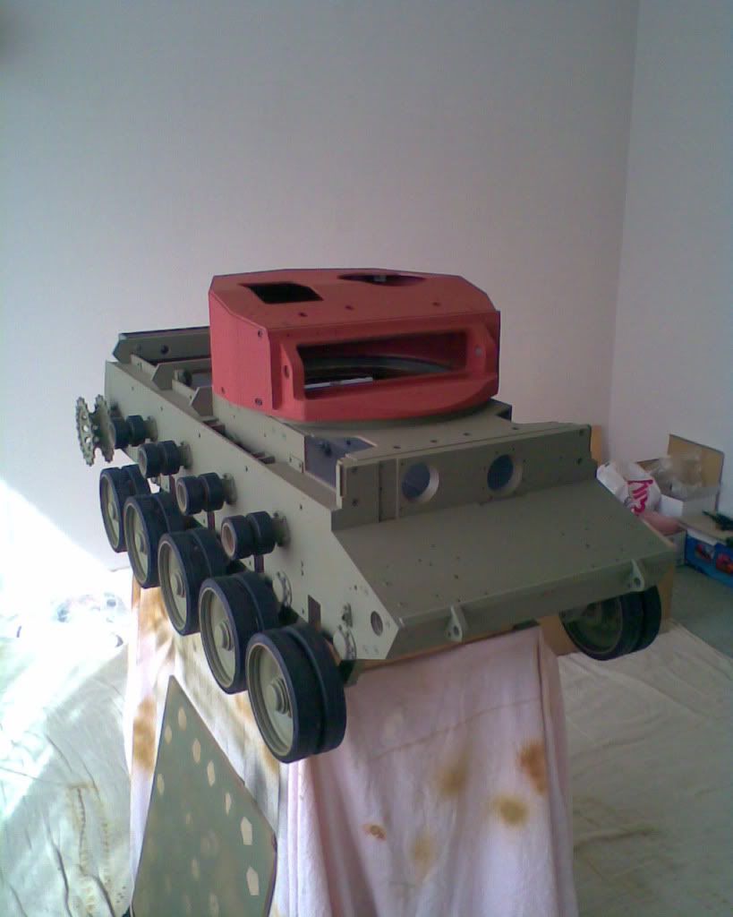
TyresFitted to Road Wheels and Return Rollers

Image

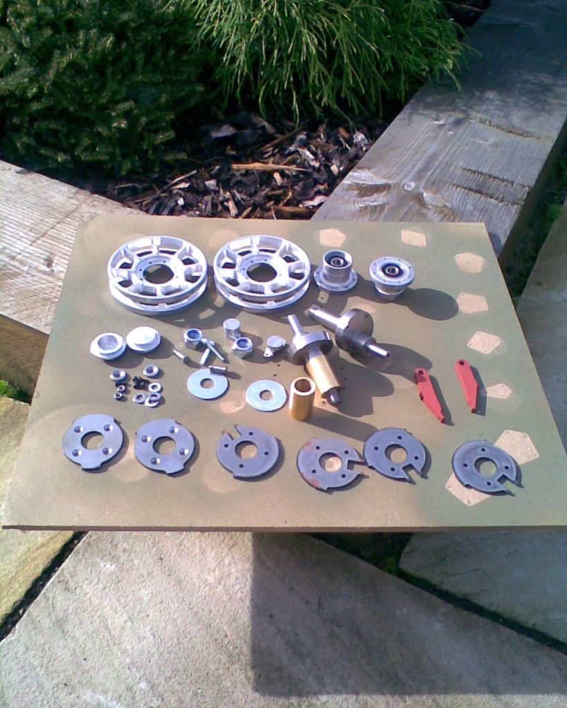
Idler Parts
Image

phil fitzpatrick
Posts: 2020
Joined: Sat Dec 12, 2009 3:38 pm
Location: Sambourne uk
Been liked: 223 times

Ratchet assembly

Post by phil fitzpatrick »

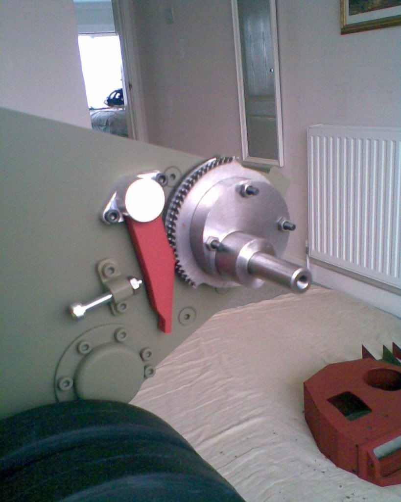
Ratchet assembly fitted to Hull
Image
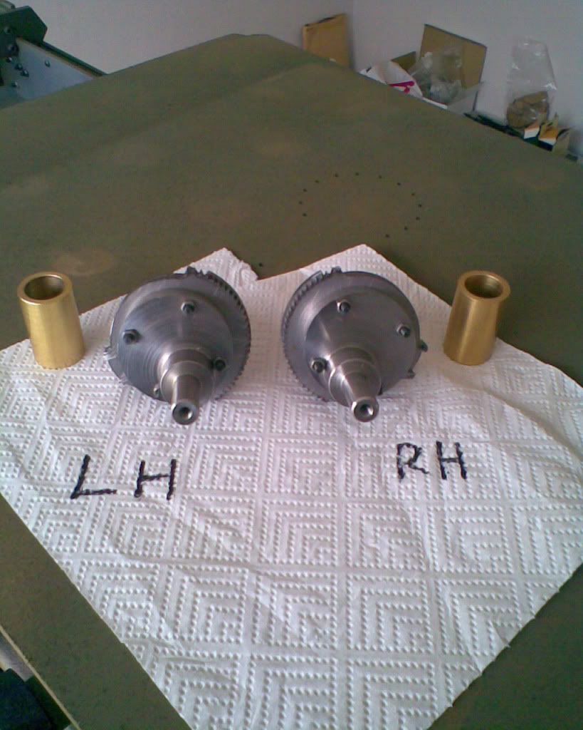
Bushes installed and Ratchets Waiting for Loctite to cure
Image

robert michael hilton
Posts: 377
Joined: Sat Apr 03, 2010 3:23 pm
Location: Welshpool, Powys

Post by robert michael hilton »

Very useful closeup photo's, Phil.....

I have solved the paint problem....now using 'satin' acrylic aerosols "British Olive Drab", from a local car parts dealer who knows a man, who knows a man, who mixes the paint for me......the big build continues......mick

phil fitzpatrick
Posts: 2020
Joined: Sat Dec 12, 2009 3:38 pm
Location: Sambourne uk
Been liked: 223 times

paint

Post by phil fitzpatrick »

Glad You've got your paint sorted out Mick
Phil

Nick Farrugia
Posts: 547
Joined: Fri Aug 28, 2009 10:08 pm
Location: South Wales Glamorgan

comet 1A

Post by Nick Farrugia »

Hi phil
very impresive front ratchet system on the comet ,your build is coming on nicely .Realy good photos ,and build.
best wishes
nick

phil fitzpatrick
Posts: 2020
Joined: Sat Dec 12, 2009 3:38 pm
Location: Sambourne uk
Been liked: 223 times

IDLERS

Post by phil fitzpatrick »

Idlers fitted
Image

phil fitzpatrick
Posts: 2020
Joined: Sat Dec 12, 2009 3:38 pm
Location: Sambourne uk
Been liked: 223 times

Ratchet assembly

Post by phil fitzpatrick »

Hi Guys
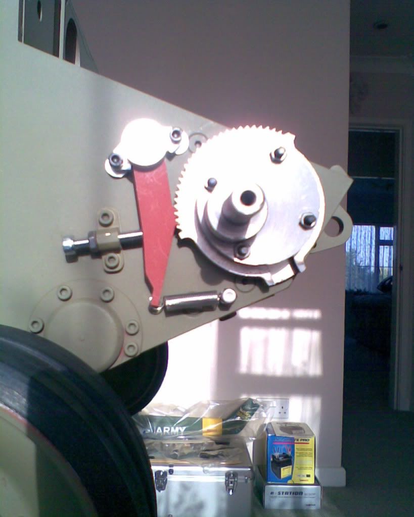
I kept wondering what the hole was for in the bottom of the ratchet,then
I found it on page 861,in the Chief Inspector of Fighting Vehicles,Comet 1
Handbook.
There was a peg in the hull and an extension spring that holds the ratchet
into mesh when the lock nuts are loosened,when the crew adjusted the
Track tension.
Which the manual says "Insert the end of the adjusting lever into one of the two slots and using the full efforts of three men,lever upwards untill the correct tension is obtained".
So I fitted a peg and found two spring to suit and switched my lock nut arround to the other side.
Image

phil fitzpatrick
Posts: 2020
Joined: Sat Dec 12, 2009 3:38 pm
Location: Sambourne uk
Been liked: 223 times

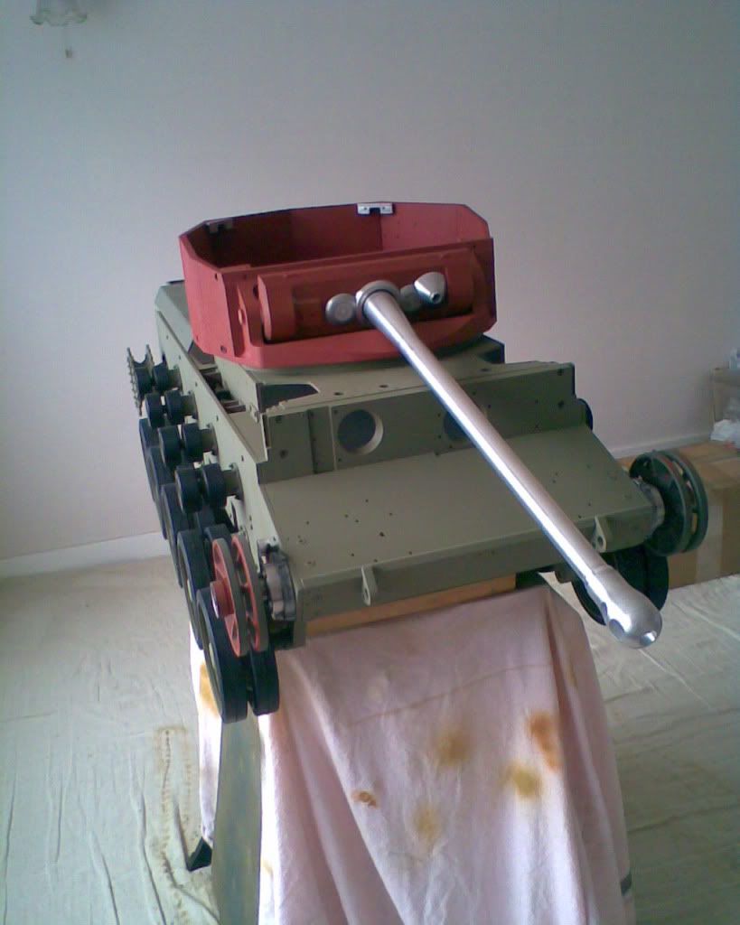
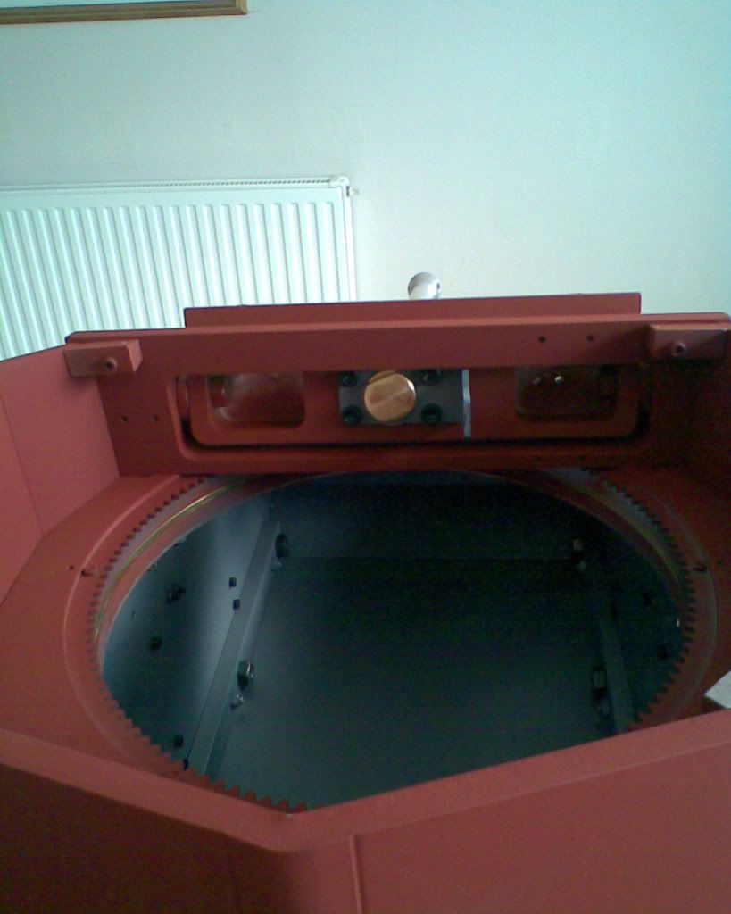
Main Gun assembled

Post by phil fitzpatrick »

Followed the advice for a gentle file of the thread on the barrel and WD40,
All went together easy.
Only one problem,I couldnt find my brass barrel retainer nut,when I came
to assemble the mantel bits and cannon,searched everywhere.
It was in the end of the barrel when I assembled it. :oops:
Image
Image

User avatar
Adrian Harris
Posts: 5103
Joined: Thu Jul 12, 2007 10:46 pm
Location: Berkshire (UK)
Has liked: 1466 times
Been liked: 1637 times

Post by Adrian Harris »

Looking good Phil :!:

Adrian

robert michael hilton
Posts: 377
Joined: Sat Apr 03, 2010 3:23 pm
Location: Welshpool, Powys

Post by robert michael hilton »

Hello Phil, I have now started to fit the suspension units....having solved the paint problem and finished painting the hull, the suspension units are also built.
Question.....bearing in mind my lack of experience in these matters. I would prefer to set the final 'spring tension' now, rather than adjust it later.
I have used the recommended thread depth for the 'nyloc' nut of 10mm.
Can I rely on this mid-range 'setting'....for general running, bearing in mind my Comet will be more of a 'show' tank.....not to be used in anger.

I did not want to dismantle and adjust this setting as when the tank is nearing completion.....mick

Paul Fairlamb

Post by Paul Fairlamb »

Hello Mick,

You are raising a question close to my thinking. My Comet now has the suspension installed and even with the outer hull sections installed, it looks as it might be possible with the front and rear side decks removed to access the adjusting nuts from above with a socket spanner.

I have substituted the 'nylocs' for a lock nut arrangement to avoid the torque problems on the suspension springs.

Also being new to tank building I wonder if anyone can advise what the objectives are with regard to setting the suspension tension.

What are we trying to achieve? Is it necessary to have the same tension on all springs or will it be biased either towards the front or back? How do we know when we have correct?, accepting of course that we want to avoid hitting the stops too often.

If you are only building towards a show model I would suggest the the tension need only be sufficient to overcome the weight of the tank as the length and setting of the track tesion will determine the ride height.

I hope this does not just make a simple task more complicated than it need be.

Paul

John Davie
Posts: 114
Joined: Wed Jan 13, 2010 8:55 am
Location: Ampthill, Bedfordshire
Been liked: 15 times

Post by John Davie »

Hallo,

I'm hoping the 'default' setting is OK. Once you've got the side panels and mudguards on it makes it a lot of work to be able to get back in to adjust them.
I have a slightly different consideration because my tanks are intended to run and get a lot of hard running.
However seeing Mark's prototype running at the open day the suspension on that worked extremely well.

John.

robert michael hilton
Posts: 377
Joined: Sat Apr 03, 2010 3:23 pm
Location: Welshpool, Powys

Post by robert michael hilton »

Thanks for your thoughts guys....

I had considered a locknut arrangement Paul....

I managed the 'nyloc' nut by holding the 'threaded 'area with a small locking wrench, to stop the rod turning.

This being my first Armortek tank.....my prefered option for the Comet is a 'parade ground' final finish, so no hard running etc,.

Thanks again , John and Paul

phil fitzpatrick
Posts: 2020
Joined: Sat Dec 12, 2009 3:38 pm
Location: Sambourne uk
Been liked: 223 times

Suspension

Post by phil fitzpatrick »

Hi Guys
I set mine as the recommended and stuck with the lock nut using a small locking wrench and a bit of cardbourd to protect the thread.
I thought I could get in easy enough with the front and rear side decks off
if I needed to when all the weight is on.
With regards to the ride height,all I could find with a quick look,is in the
Armor Photo Galery book in the 1/48 scale drawing it measues 10mm
Which would make 480mm = 80mm 1/6 scale.
I will keep looking otherwise I'll see what mine measues when its fully laden.
Cheers
Phil

phil fitzpatrick
Posts: 2020
Joined: Sat Dec 12, 2009 3:38 pm
Location: Sambourne uk
Been liked: 223 times

Sprocket caps

Post by phil fitzpatrick »

Made an Armoured cover plate for my Sprocket caps
Image

Post Reply