It seems ages since my last post for a variety of reasons. Too cold outside now to continue with the stillbrew; will have to wait now until better weather appears.
There's been lots of talk about batteries and regeneration with some clearly entrenched in their positions. From my own perspective, I'd like to take advantage of the benefits of LiFePO4 but have concerns regarding the regen current. There appears to be no measurement data out there wrt regen current to make an informed decision although one could potentially say, its related to the speed of the motor. Many think there isn't any regen current since the tanks don't freewheel because of the gearboxes; they do, it just happens so fast they don't see it and in the meantime, over 1000 current pulses have been applied to the battery.
Looking at a few Safety Data sheets for LiFePO4 batteries indicates the following:
1. Do not connect any other power sources to the battery other than the chargers supplied with the battery pack
2. Do not exceed the maximum charge current of the battery otherwise damage may occur
As far as i am aware, the max charge current of a LiFePO4 battery is 1C...so for a 20Ah battery, that would be 20 Amps. Hear's another interesting paragraph that I found posted on the forum from Armortek back in 2011:
The regenerative braking was introduced with the module based Armortek Speed Controller, about a year ago. This is a digital speed controller and it works by sending pulses of power to the motor. In the gaps between the pulses, it sends the power generated by the motors back to the batteries to recharge them. The standard EMD gearbox is between 60 and 65% efficient, depending upon speed. Because of this about 30% of the battery power is lost when driving and when recharging. The new gearbox is 90 to 95% efficient. This means it both uses less power to drive, and recovers more power to regenerate.
Now Chieftain has two speed controller modules; one for the track motors (Unit A) and one for the turret elevation and traverse (Unit B). Clearly, Unit A has to be capable of handling larger currents. The manufacturers blurb indicates that in both controllers, the regen occurs when the motor slows down. Unit B however, also supplies a regen when in reverse!
Certainly with respect to Unit A, it is feasible that a current larger than 1C could be supplied to the battery but the amplitude of this current is really dependent on the motor speed. There is so much grey here, and very little black and white so to speak.
Until more is known, I believe the best thing to do is to get rid of the regen current if I want to use LiFePO4 batteries so my investment is protected until more is known. Now it is possible to do that on Unit A!
Unit A was opened an all the wiring was removed from the terminals (this facilitates removal of the controller from the bottom of the case) followed by undoing and removing the nuts and bolts holding the controller to the bottom of the case. The controller can then be slid sideways out of the casing. That's the warranty gone

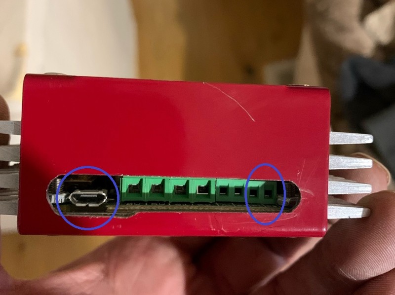
The slot at the RC end was then elongated either end as shown below; anyone know the paint code

Unit A was then reassembled. Elongating the slot allows access to the USB port on the controller and the terminals P1 and P2 to which resistor networks will be connected to (one for each terminal) to allow the regen current to be dissipated as heat: The value of each resistor network is calculated using the lesser of the nominal motor current or 8A!

The USB port will allow access to the advanced Options menu via a software package. This allows us to set up things like battery type, voltage and current limits as to when the controller shuts down as well as enabling the voltage clamping on terminals P1 and P2. It also has a diagnostics tab where real-time data from the controller can be obtained and recorded. That only leaves one thing to do and that is to change the DIP switch Position 3 switch to on (Power Supply). Any regen current from the track motors should now be dissipated through the resistor networks on P1 and P2. Should more information come to light that makes regen more favourable, its a simple matter to reprogram and disconnect the resistor networks.
Unfortunately, unit B isn't as flexible and I don't think that the regen can be shut off. There is no USB port to connect too. That said, it is I believe most unlikely to exceed 1C so could be left as is or replaced with a controller that doesn't have regen. If its left, then DIP switch Position 3 will need to be set to Lithium.
Please note, if you do any of the above, you will invalidate your warranty. I have left certain information out to try and ensure only those competent to do so may undertake this.
Merry Christmas to all