Page 18 of 28

Isolating switch

Posted: Wed Feb 16, 2011 8:40 pm
by phil fitzpatrick
Hi Mick
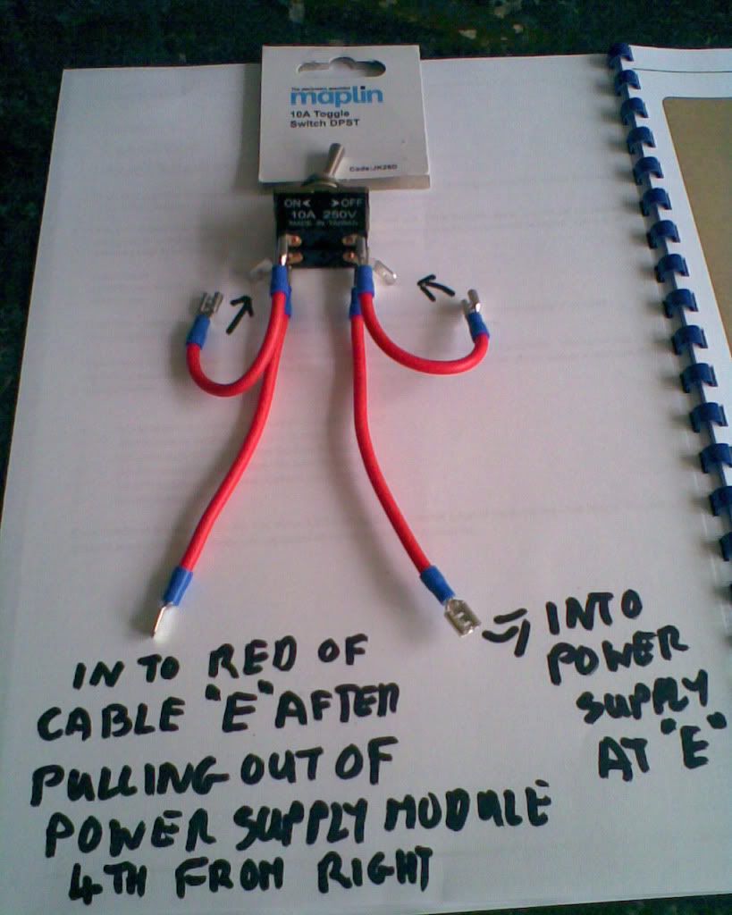
Here is the Maplin 16 amp switch and how to wire it up for a 32
amp Isolator if you decide on one.
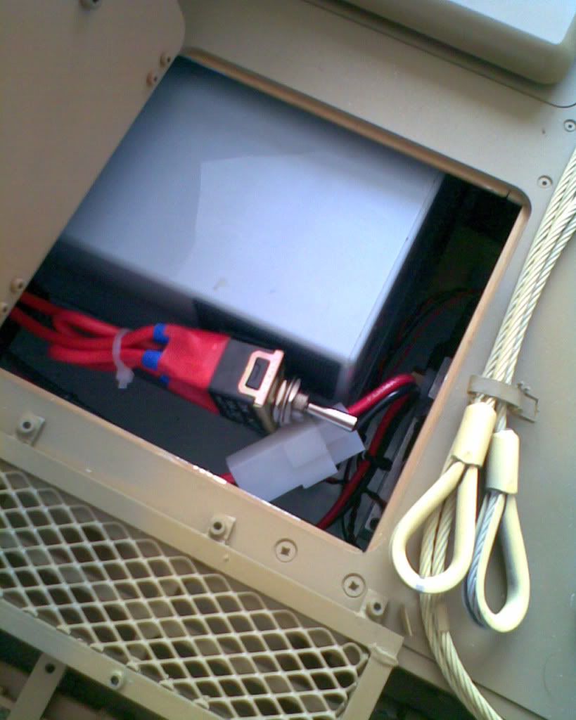
Its all crimp terminals so no soldering als a picture of where I
put it at the rear in the Panzer,where you will see the battery
connector and just out of site is the charge lead under the little shelf.
Cheers
Phil

Image
Image

Posted: Thu Feb 17, 2011 4:44 pm
by robert michael hilton
Thanks Phil, I can follow those instructions....I will take it one stage at a time....so not to get my wiring mixed up. I have read your post again..and again.......and again.

Phil, just a side issue....Steve's M/Gs.

My M/G in the main body, fitted fine with a little filing and lies in the cradle...no problem. The M/G in the turret is a different matter and is far to big for the cradle.
I have not installed this turret M/G yet. How is yours fitted....I have looked at your post and can see the turret M/G in the turret. did you remove the back of the cradle??

I will write up a step by step guide for myself before I begin installing the flash etc.
I have the same urge to crack on, that I had, when the boxed up Comet arrived, need to take my time......Mick

Turret MG

Posted: Thu Feb 17, 2011 5:14 pm
by phil fitzpatrick
Hi Mick
Yes it needs trimming down.
Lucky that I hadnt thrown the bit away yet that I cut off so I was
able to give you the measurement of what I cut off as a guide
for you.
It was 18 mm off the back of the gun and I had to shamfer the
back of the gun to sit against the rounded bit at the back of the
MG Armor.
I also had to cut out the back of the Armor where the hole is,I
cut down from the top of the back to the base leaving just a safe amount clear of the fixing holes,otherwise I couldnt have got it in.
I didnt fit the U shaped cradle it wouldnt sit right.
I was going to just cut the front of the side off it and glue them
in place but I didnt get round to it and now with my mantlet cover
and cam nets it doesnt show.
Also you will notice I had put the bar acroos the top of the back
of the Armor this is drilled and tapped and so holdes the gun in
and also hides the missing bit aswell.
I seem to remember that I could only cut that amount of 18mm off
because the cables for the led wouldnt pull out any further with
the little terminals on.
If any body spots my missing bit I can still slide a bit in from the front but its quite disguised enough at the moment.
Hope thats a help,just do a bit at a time with the cutting and
filing and keep trying it untill the barrel goes through the hole and
it sits flat.
Cheers
Phil

Posted: Fri Feb 18, 2011 6:45 pm
by robert michael hilton
Hello phil, thanks for everything, I will let you know how I get on over the next week.

Question, I would like some help with setting up the Futaba 7c, in respect of the gun flash/M/Gs, etc,. I have searched in vain for instructions, I believe they are there somewhere on this Forum.
I seem to remember a system where you use two switches on the TX simultaneously to achieve main gun flash and sound.??. I don't suppose it is possible using one switch to have both flash and sound. This system may be too complex. Anyway I would appreciate your thoughts

Over the weekend I will prepare the gun to receive the flash, then connect the charging lead, I will leave the isolate switch till later.
Thanks again Mick

MG's and radio

Posted: Fri Feb 18, 2011 7:38 pm
by phil fitzpatrick
Hi Mick
At the moment you dont need to alter your radio.
With only your hull Mg installed you could just connect it straight
to your 3 pins on the Amplifier.
Try it first with the white lead closest to the volume knob,thats
the way round mine is so it should flash your MG when you operate the MG sound % back from centre and one forward to fire.
If you was fitting wiring both Mg's you need a Y lead,see the
drawing I sent you a bit further back for splitting the Guns up.
But unless you are splitting the Guns just put one Gun in each of
The Y lead sockets.
THen when you operate the MG sound both MG's will flash.
You will only need to alter your radio by asigning channel 7 to
SW G if you decide to split them and I can let you have a
simpler explanation on how to do that at the time.
Because you will be having your Main gun flash soon it is best to
fit your 2 Y leads now,as the drawing I posted for you on the
Main Gun flash.
Your 1 MG will go into any of the sockets and work as long as
you remember the way round the lead goes as before it will work
Then when you get to the Main gun flash if you see the
instructions it goes into the socket reversed with the black lead
oposite the white.
With the Main Gun Flash you dont have to do anything with your
radio,It will flash when you operate your Gun sound,I dont need
to tell you how to do that,it sounds like you are a regular firer :lol:
Start off by fitting your 2 Y leads,connect up your Hull MG and
confirm that works.
If you are not fitting your Turret Mg yet its best not to try that to
see if it works because you dont want to put the futaba plug on it
yet because you need to draw out the led cable as far as you can
into the barrel so you dont chop it off,but it should work ok
anyway.
With your MG confirmed as working you can forget that bit and
crack on with your Main Gun Flash as the drawing.
Sorry this is long winded but if you have decided you dont mind
the 2 Mgs firing at the same time you dont need to do any
programming with your radio yet.
You can split the MG's later when you are ready.
Cheers
Phil
Splitting up the 2 MG's

Posted: Fri Feb 18, 2011 7:56 pm
by phil fitzpatrick
Hi Mick
I just had a brain storm as I was putting my Pizza and chips in
the oven,and more smoke came out my ears than your Armortek
Smoker.
I have a spare 24 vdcTYCO Relay from my Panzer111 exhaust,its the little black box with your yellow and blue wire going to it.
So when you are ready just post me 2 futaba extension leads
and I can do the rest for nothing and you will only have to plug
things in,with a simpler drawing still.
The radio I can explain easy for you.
Let me know when you are ready its an offer you cant refuse :lol:
You will have the harder job getting the Gun into your MG Armor
Cheers
Phil

Posted: Sat Feb 19, 2011 1:34 pm
by robert michael hilton
Hello Phil, believe it or not I can understand your instructions, they are very clear. I will take you up on your offer re: turret M/G wiring. Thank you.

Two points....I forgot to reimburse you for P & P.....I will send a cheque on Monday.

Second point....I am about to connect the wiring for the main gun. I have fitted the Halogen Bulb in the muzzle break and drilled the barrel retainer nut.....all fittings are good.

Now as a temporary measure I have connected the charging lead that came with the Accumate.... to my batteries....however the lead is to short and has a waterproof cover.

When I came to connect a pre-wired Tamiya connector to the waterproof plug...the red/black wires were reversed.
I know enough about electronics to say that is just wrong...the pos+ red lead should run from the battery to the pos+red on the Timer.
I could just reverse the red and black leads in the Tamiya connector.
Is that acceptable.....as you know the Tamiya connector is designed so you cannot reverse them by accident.
This is only a temp' measure....so I guess the best way is to make a complete lead that runs from battery to Timer....this lead will serve as 'charging' as well as 'timer'. I will give it a break now, and clear my mind.

By the way, all the 'sounds' 'turret turn' 'gun elevation' 'M/G' etc, are working. There are wires everywhere :roll:

Hope you can understand...Mick

electrics

Posted: Sat Feb 19, 2011 4:00 pm
by phil fitzpatrick
Welldone Mick youve got on well.
Dont worry about the post age chq its fine.
If you send us 2 servo extension leads I will make the relay
for you so you can fit it when you like.
I extended my Acumate charging lead to reach the back with
crimp terminals.
Yes the polarity differs with Tammiya and accumate.
I dont think its very easy to get those terminals out of the
connector because of the spike each side.
You could just mark the other end of the lead that will connect to your gun flash relays,with coloured shrink tube or insulation tape untill you can make a new one up for your own peace of mind.
Cheers
Phil

Posted: Sat Feb 19, 2011 4:04 pm
by robert michael hilton
Hello Phil, well main gun 'flash'not working as yet...I believe I have all the connections as per the drawing.

This answer will probably be simple....not cracked it yet. I have one power lead now from the battery ( removed the Accumate lead ) to the Timer....I have the first Y lead on the AMP, with white lead nearest the volume switch. The 1st M/G is connected and working. I have connected the second Y lead, this is not connected to the 2nd M/G.

I have reversed the servo lead from the Relay/Timer, and fitted it into the the second Y lead.

M/G flashes...main gun boom....no flash??? I will take a break now....gather my thoughts....mick

Gun Flash

Posted: Sat Feb 19, 2011 5:53 pm
by phil fitzpatrick
Hi Mick
A few things to check if you havent done already.
The second Y lead connected to the first has the cables matched up colour to colour.
The servo lead connected to the 2 seperate terminals on the
relay is pluged in so Black is to white and white to black.
This one sounds daft but check you have the battery lead connected to the 24v side and not the 12 v.
Did your electrician freind show you how to use your meter.
You could verify that there is 24 volts at the 2 terminals on the left of the block of 4.
Two more little things,there was a little lime green instruction sheet for the timer relay in the box.
During transport the relay inside the timer can swich over so the
normaly open contacts are closed etc.
Too solve this you need to connect the 24 volt from your battery
to the big timer relay at terminals A1 and A2.
The black wire is already connected to A2 via the terminals so all
you would need to do is connect a wire from the red wire at the
4 terminals that your battery is connected to for the 2 seconds.
When you do this a little green light comes on at the top of the timer by the dial and switches.
The other one is when you operate the Main gun sound the little
green light should also come on briefly,if it does but the Halogen doesnt flash try turning the little timer dial slightly clockwise.
Let me know if any of that helps you out.
Cheers
Phil

Posted: Sat Feb 19, 2011 7:22 pm
by robert michael hilton
Hello Phil, I have tested for 24v....the two batteries are connected as Armortek instructions. I have connected a red lead from one battery to the red lead on the timer....I have connected a black lead from the other battery to the black lead on the timer.

I have made sure the servo lead is reversed, at the relay, black to white/white to black.

I have put a red lead from the 24v red to A1 hold for two seconds black is already connected.

The Timer shows a green light and clicks ...... The halogen light comes on bright at the muzzle break.

I have switched on TX.... switched on RX......M/G...ok....main gun....boom...ok.... no 'flash'.

Turned timer clockwise slightly....still no flash.

Mick

Posted: Sat Feb 19, 2011 7:27 pm
by robert michael hilton
Phil...I have read your post again...one point, when I connect the red lead from the batteries to A1 on the timer...the green light and the flash at the mussle break stay on, until I disconnect the red lead....is that ok...Mick

Flash

Posted: Sat Feb 19, 2011 8:03 pm
by phil fitzpatrick
Hi Mick
Yes it would stay on so all that bit is ok.
Does the little green light come on breifly when you operate
the gun sound?
I have just sent you a PM.
Cheers
Phil

Posted: Wed Feb 23, 2011 1:55 pm
by robert michael hilton
Hello Phil....all is well, in the dinning room. I have fitted the limit switches, takes awhile to get the elevation right. After greasing the thread and a spot of oil on the movement the gun elevation is fine.

Tried the main gun...just a few times.....6/7.....works a treat. I will split the M/Gs tomorrow....and run the smoker. All windows in the open position, fan set ....to clear the smoke.

So, all's well that ends well....thanks again for all your help Phil. I have tided up some of the wiring....nice to have the rear end ship shape, oops! wrong model.

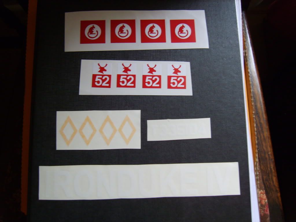
Should be able to move on now and complete the main Comet build. The 'timeline' is good. I will also post a photo of my decals from Pyramid Models. Very helpful site.....Mick

Posted: Wed Feb 23, 2011 2:07 pm
by robert michael hilton
Difficult to see IRON DUKE 1V....

Image