Page 12 of 43
Posted: Mon Sep 28, 2009 10:01 pm
by Derek Attree
Hi Stephen
That look stunning.
Thanks for posting the pictures
Derek
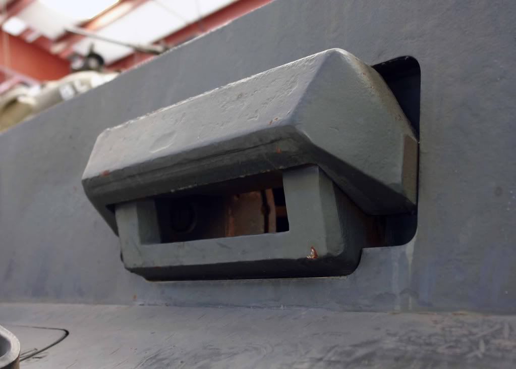
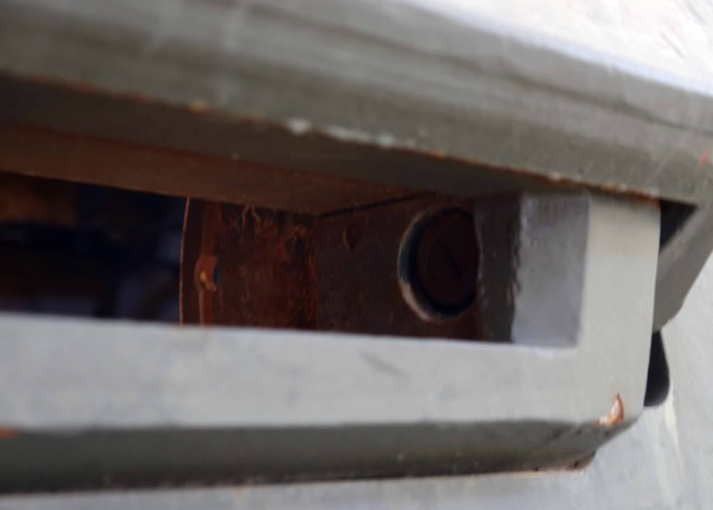
Driver's Vision Port - Part 2
Posted: Sat Oct 03, 2009 7:35 pm
by Stephen White
Second part of the driver's vision port:


Still some fitting work to line up the hinge points and achieve the right movement and then fitting to the hull front plate but here's an idea of how it will look:


Regards
Stephen
Posted: Sat Oct 03, 2009 10:50 pm
by Tim Bowman
Outstanding work Stephen


as usual.
Looks like the real thing!


Tim
Posted: Sun Oct 04, 2009 4:21 am
by Stephen White
Tim - thanks as ever. That's the first time I've seen a photo which shows the location of the hinge pin. Although it's shown on an original drawing I've got, I haven't seen confirmation in the flesh before and you can't see it on the Bovington vehicle.
Regards
Stephen
Posted: Sun Oct 04, 2009 11:15 am
by Jeffrey Goff
Hi Stephen, fabulous work on the drivers vision block, you keep setting the bar higher, and are inspirational to all of us following
keep up the good work
regards
Jeff
Posted: Tue Oct 06, 2009 8:31 pm
by Robert E Morey
Stephen,
Excellent machine work. I'm amazed how you translated that maze of lines and numbers (on drawing) into a beautiful functional piece. Fine job. Those details will really make a difference on the finished model.
Bob
Posted: Sun Oct 11, 2009 5:31 pm
by Stephen White
The almost finished article. Just the glass to add when the acrylic arrives.


Also machined the two holes for the driver's reversionary periscope and some detail on the hatches.
Regards
Stephen
Posted: Sun Oct 11, 2009 8:35 pm
by Dale jordan
Hi Stephen ... Fantastic work . You sure are getting your moneys worth out of your kit... My Panzer tracts 3-3 turned up yesterday . This is a must have to go with our kits ... great scale drawing ..Dale
Kugelblende 50
Posted: Sun Oct 18, 2009 8:35 pm
by Stephen White
The hull machine gun ball mount (Kugelblende 50) was much deeper than the kit part and the ball sat further back within the mount. The aperture was off-centre and of a rectangular shape.
So:
I've inserted a 5.1mm thick disk to give the mount the additional depth:


I've applied the cast surface to the ball itself using a wire polishing brush which seems to pit the surface very subtly and smoothed the surface of the mount ready for applying the cast surface. I've alsp cut the groove around the mount which was used to secure the fabric covering sleeve for the MG:


The inside of the mount requires filling with Milliput to provide the internal depth - shaping next week. Last job was to add an acrylic lens to the driver's vision port.
Regards
Stephen
Kugelblende 50 and MG34T
Posted: Sun Oct 25, 2009 5:31 pm
by Stephen White
The finished hull MG ball mount (Kugelblende 50):


To complete the picture, a new MG 34T barrel:

Regards
Stephen
Posted: Sun Oct 25, 2009 8:49 pm
by Robert E Morey
Excellent work Stephen. The ball mount looks so much better. Did you make the MG barrel? It looks awesome. Keep the details coming!
Bob
Posted: Sun Oct 25, 2009 9:09 pm
by Stephen White
Hi Bob - yes the MG is turned from 10mm ally bar stock. It's the first piece of work I've had to try out a rotary table on the mill - trouble is now I can see a stack of things to use it for. The next project will probably have to be the brake vent housings.
Then back to the roadwheels. I've now got the correct profile having chanced upon a technical report from 1943 in the Tank Museum Library. A captured roadwheel was sectioned to analyse the metal and the report had a picture of the cut through profile.
Best regards
Stephen
Posted: Mon Oct 26, 2009 10:38 pm
by Lawrence Godson
Hello Stephen,
Continuing to marvel at your work. Has anything occurred relative to the possibility of producing the front hinges?
Thanks
Brake Vents
Posted: Sun Nov 08, 2009 11:27 pm
by Stephen White
Next up the brake vents on the front hull. Started machining but needed some head scratching to find a way to hold the work:

I was waiting for the work to disappear across the workshop but it worked in the end.
Two out of three finished pieces, just the top vent to come:


Regards
Stephen
HOLDING
Posted: Mon Nov 09, 2009 3:24 pm
by Graham Ord
Hi Stephen
Its nice to see you using some pretty unconventional holding methods on your mill. Some of the set ups I also employed were strange to say the least, but they work and thats the enjoyment that one gets!!!


