Page 2 of 3
Posted: Sun Aug 10, 2008 11:35 pm
by Robert E Morey
Cedric,
Your hull is looking great. Better to slice up the top deck now than later! Don't worry it will look great in a short time! Keep going slowly -take your time!
Bob
Posted: Mon Aug 11, 2008 12:28 am
by Tim Bowman
Robert E Morey wrote:Better to slice up the top deck now than later!
Wise words.

Cedric,
Great job. It's looking good. As Lee said, go slow with fasteners and it will come together.
Tim
Posted: Mon Aug 11, 2008 8:07 am
by Kent Wiik
Nice work Cedric!
And as the Bob say, go slow and take your time.
Do it proper and have fun the whole time - it will be well worth it in the end.
Can’t judge it from the photos but I assume you have done the front plate a bit higher then the others?
Please keep the photos coming.
Best wishes
Kent
Posted: Sat Aug 16, 2008 4:05 pm
by cedric meyer
Yes, exactly. I used a 4 mm alu plate... It looks really scale, i'll make a bigger picture...
I'm still sceptic about one thing, now, after few fitting and adjustments, all fit...but, once all screws are tight (together at the same time), i have a big gap on both side of the rear plate, between rear plate and pannier side...
Panther's builders, is that normal? Do you fill this gap with JB weld for exemple?
Posted: Sat Aug 16, 2008 5:35 pm
by Robert E Morey
Cedric,
I actually filed the rear hull plates some to taper them - and get better fit. Otherwise you have gaps in the rear plate. Same situation on the turret - I filed the rear plate locking tabs to get the turret sides to fit better. It takes a bit of work but its worth it. I also epoxied all joints after bolting them together..
Keep the photos coming!
Bob
Posted: Fri Sep 26, 2008 4:12 pm
by cedric meyer
I would need again an advise, do you hide with JB weld fasteners under chasis and on the side? Like we hide some visible fasteners on turret for exemple....
I'm talking about fasteners who tight the suspension bar to the chassis plate and to the side hull. If yes then it's not possible to make any further replacement?
Posted: Sun Sep 28, 2008 6:46 pm
by Robert E Morey
Cedric,
I cover the screw holes holding the hull and turret together with milliput. I did not cover the screws to remove the suspension bar or torsion bars, nor the screws holding the bar that has the brass bushings in it. Hope that helps? I don't plan on taking the hull or tutrret apart. But you may need to take the torsion bars and suspension arms out. And you may need to remove the bar with brass bushings in it? Although hopefully not, but it would be good to not cover these screws just in case.
Posted: Tue Feb 10, 2009 7:06 pm
by cedric meyer
Hello everybody, i keep on working on my modified deck, and on assembling the hull and adding extra details (kent's work is a great inspiration but it never ends

and everytimes i think i'll put the hull together, i have to unscrew everything to detail more).
I'm very slow because i don't have so much time available but once all i'm doing will be completed, the hull will be finished in a snap..
One question, is there somebody in there who can tell me how the fuel filler cap and the coolant filler cap get in and out?? The base is welded on the engine plate but how does it work in real, how the crew was opening the hatches?? I want to turn new ones...than i can open and close (if possible) like the real thing...
Thank you for any informations or pictures...
Ced.
Posted: Tue Feb 10, 2009 8:01 pm
by Derek Attree
hi Cederic
The fuel filler was an armoured cover that has a key in the top and unscrewed under this was a filler pipe the key was square section a bit like a lathe chuck key.
Hope this helps
Derek
Posted: Tue Feb 10, 2009 9:47 pm
by cedric meyer
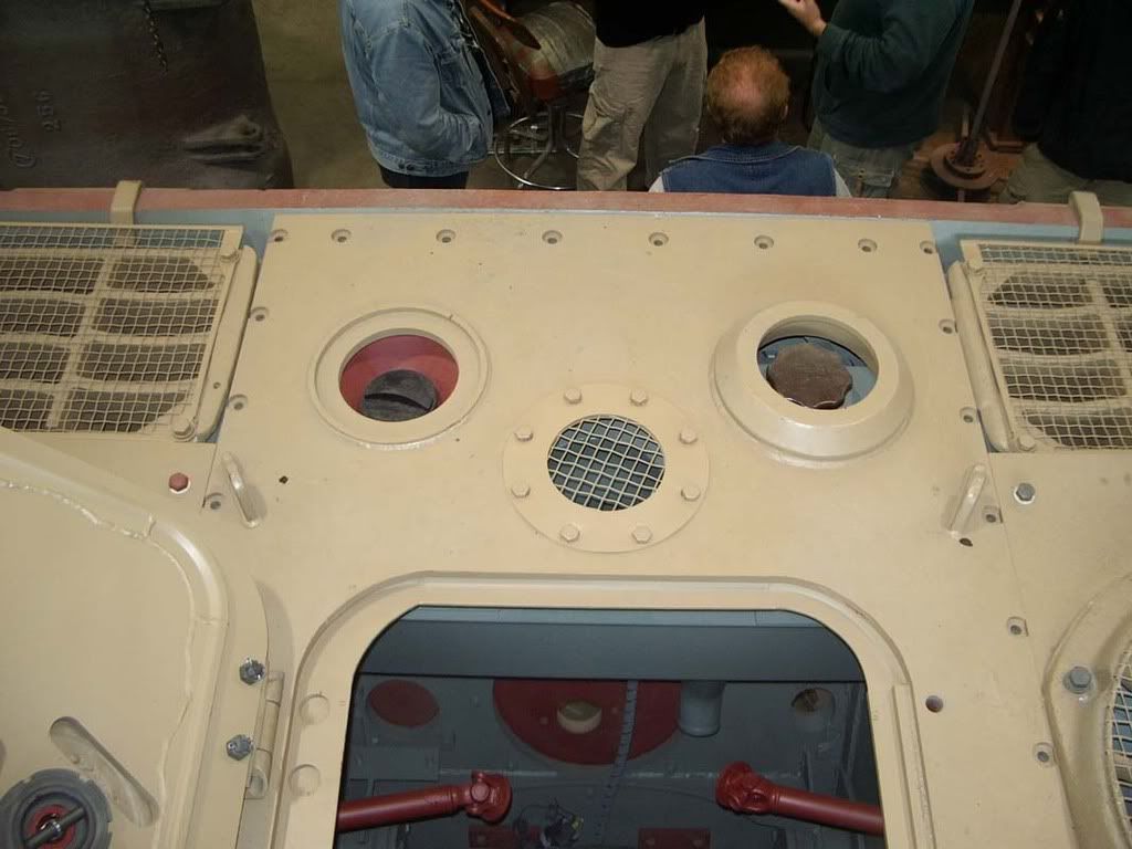
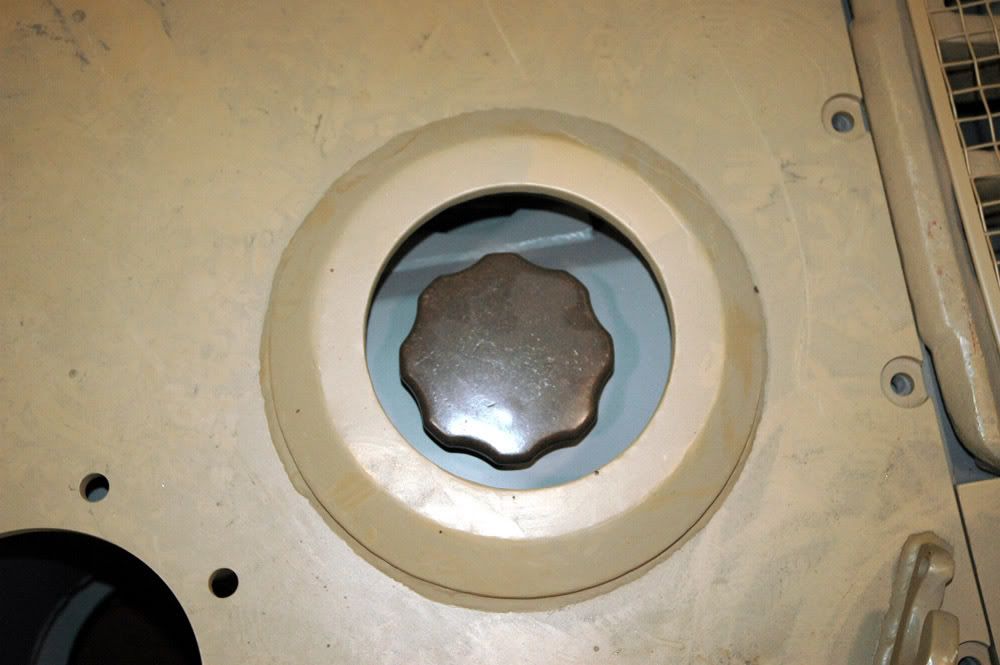
Thank you for explaining me the way it works... Have a look at this picture, on one side the armored cover is not welded but on the other side yes, how the cap come into it?? Yous would have to "turn it? as a big screw??
On the close up, i don't see the way it come into that!!
Sorry,i probably sound stupide, but i don't get it!
Ced.
Posted: Tue Feb 10, 2009 10:36 pm
by Derek Attree
Cedric there is a metal cover that goes in the bib hole over the filler cap shown in you picture.
It has a square hole in it for a key on the pictures I have it is a screw fit
but like all these details it is possable that your pictures are of a different fitting.
If you have it the ryton book panther in detail has some good photos of this detail unfortunatly I dont have a scanner.
May be one for Kent
Derek
Posted: Tue Feb 10, 2009 10:46 pm
by Tim Bowman
Hi Cedric
Here's the photo Derek is refering to.
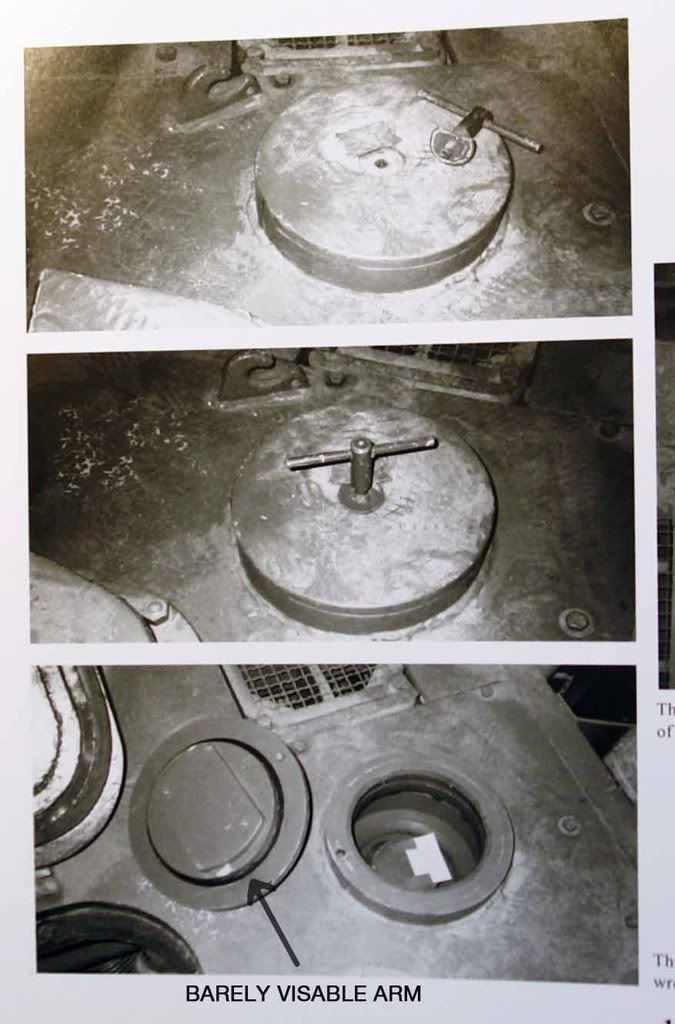
Looks like there are some arms that extend when handle is rotated.(one arm looks barely visible in last picture in retracted position) I'm assuming it functions similar to hatch locks on German vehicles. The cover plate on the bottom is covering the mechanism. The round tab on the handle/key rotates under the welded tab to allow lifting of cap.
Hope that helps
Kind regards
Tim
Posted: Fri Feb 13, 2009 7:36 am
by Per Sonnervik
Hi Cedric,
About the filler cap it works like this;

When you turn the key the two lever arms (see arrows) is activated (they fit in a groove on the inside of the protuding ring welded to the hull). The cap has a peg (see 1) which fits in the hole on the protuding ring, see photos in Tim´s post.
Remember that this is for the Tiger II, JagdTiger and Panther G, the Panther D and A are sligthly different.
Keep up the good work with your Panther.
Per
Posted: Sun Feb 15, 2009 8:20 pm
by cedric meyer
thank you very much for all that details, it's amazing what you know guys... I will see what is doingable...
ced
few improvements
Posted: Fri Mar 13, 2009 9:25 pm
by cedric meyer


