Sarah's Panzer III build
-
David Gray
- Posts: 289
- Joined: Tue Jul 24, 2007 7:22 pm
- Location: chesterfield derbyshire
- Been liked: 1 time
-
Brian Leach
- Posts: 363
- Joined: Tue Nov 18, 2008 4:15 pm
- Location: Auburn, Wa USA
- Been liked: 3 times
-
Dennis Jones
- Posts: 884
- Joined: Wed Feb 04, 2009 11:19 am
- Location: Poole, Dorset
- Has liked: 10 times
- Been liked: 218 times
-
Sarah Frazer
- Posts: 202
- Joined: Sat Oct 17, 2009 8:12 am
- Location: Bristol
- Been liked: 2 times
Hi Guys,
Hi David, the plastic strip I used was Plastruct 0.5mm x 1.5mm Styrene Strip, pack number 90723. The pack comes with ten pieces, though I only used three.
Thanks for the nice comments Brian .
.
Hi Dennis, I didn't get to the Great Dorset Steam Fair, the Jeep needs a little work to get it through the MOT and I'm not up to crawling under the Jeep yet. Looking forward to driving it again
Regards,
Sarah
Hi David, the plastic strip I used was Plastruct 0.5mm x 1.5mm Styrene Strip, pack number 90723. The pack comes with ten pieces, though I only used three.
Thanks for the nice comments Brian
Hi Dennis, I didn't get to the Great Dorset Steam Fair, the Jeep needs a little work to get it through the MOT and I'm not up to crawling under the Jeep yet. Looking forward to driving it again
Regards,
Sarah
'I reject your reality and substitute my own'
-
David Gray
- Posts: 289
- Joined: Tue Jul 24, 2007 7:22 pm
- Location: chesterfield derbyshire
- Been liked: 1 time
-
Sarah Frazer
- Posts: 202
- Joined: Sat Oct 17, 2009 8:12 am
- Location: Bristol
- Been liked: 2 times
Hi Guys,
I've done more on my Panzer III
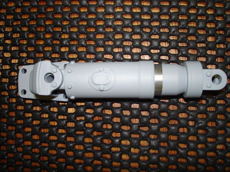
The suspension units are finished, they just need the base coat and fitting.
I've re-profiled the Road wheels and I'm glad they are finished.
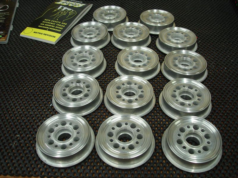
As the second batch of the Panzer III's have had the inner part of the Road Wheel re-profiled, I have only re-profiled the outer edges.
I copied Stephen's idea of using a hub/carrier for the wheels.
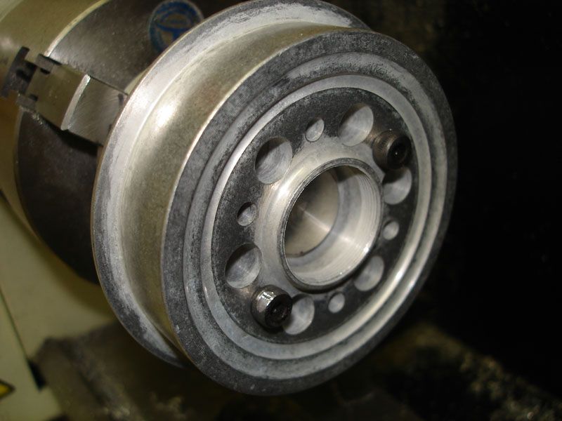
I used a profiling tool to remove the 'step' section, giving it a nice radius like the full size wheels. To enable the tools to access the edge of the Road Wheels, I had to machine the far side of the wheel and run the Lathe in reverse.
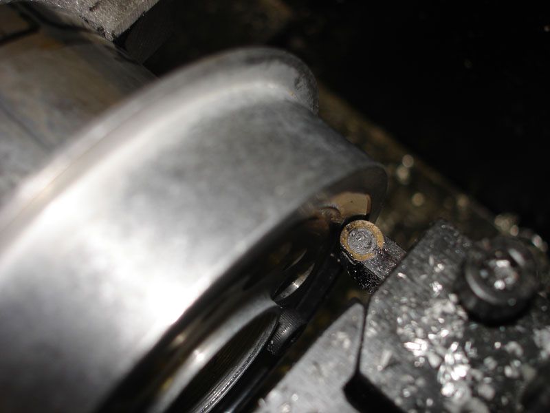
Then I used a thread cutting tool to give the impression of a 'split rim'.
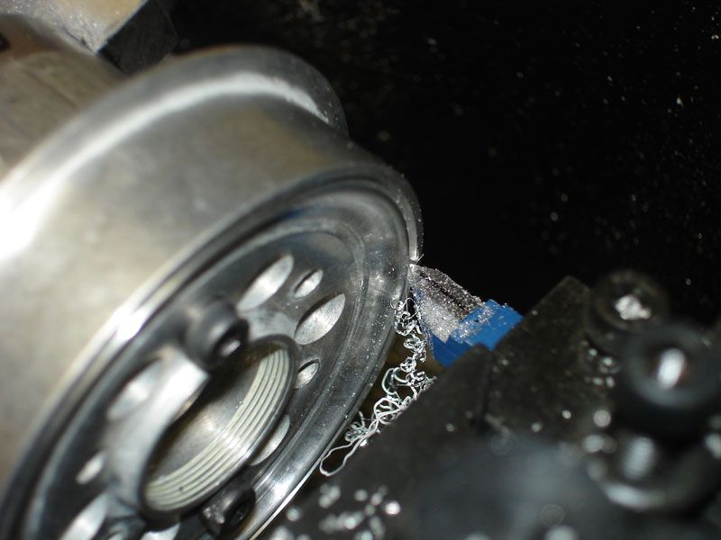
Then a bit of emery paper to round any sharp edges.
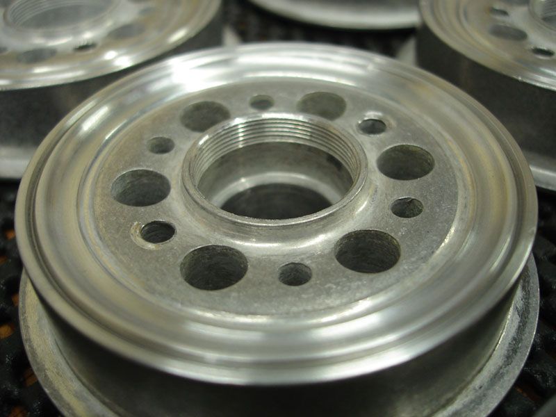
Now I need to cut lots of 4mm brass tubes........
Regards,
Sarah
I've done more on my Panzer III
The suspension units are finished, they just need the base coat and fitting.

I've re-profiled the Road wheels and I'm glad they are finished.

As the second batch of the Panzer III's have had the inner part of the Road Wheel re-profiled, I have only re-profiled the outer edges.
I copied Stephen's idea of using a hub/carrier for the wheels.

I used a profiling tool to remove the 'step' section, giving it a nice radius like the full size wheels. To enable the tools to access the edge of the Road Wheels, I had to machine the far side of the wheel and run the Lathe in reverse.

Then I used a thread cutting tool to give the impression of a 'split rim'.

Then a bit of emery paper to round any sharp edges.

Now I need to cut lots of 4mm brass tubes........
Regards,
Sarah
Last edited by Sarah Frazer on Sat Oct 24, 2015 12:55 am, edited 4 times in total.
'I reject your reality and substitute my own'
-
Stephen White
- Site Admin
- Posts: 3100
- Joined: Sat Oct 11, 2008 7:05 pm
- Location: Dorset
- Has liked: 983 times
- Been liked: 2047 times
- Contact:
-
Sarah Frazer
- Posts: 202
- Joined: Sat Oct 17, 2009 8:12 am
- Location: Bristol
- Been liked: 2 times
Re: Sarah's Panzer III build
Hi Guys,
Back with the Panzer III at last!
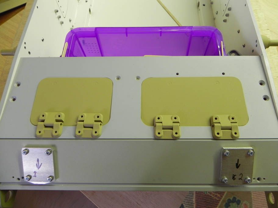
The Front Deck was ready to fit, but I didn't leave enough of a gap for the paint as one of the hatches is now catching.
I did a 3D CAD file for the Suspension Guides and had a set 3D printed. I was a little disappointed with the finish of the 3D printed parts, but a little filler soon gets the finish sorted.
Regards,
Sarah
Back with the Panzer III at last!
The Front Deck was ready to fit, but I didn't leave enough of a gap for the paint as one of the hatches is now catching.

I did a 3D CAD file for the Suspension Guides and had a set 3D printed. I was a little disappointed with the finish of the 3D printed parts, but a little filler soon gets the finish sorted.

Regards,
Sarah
Last edited by Sarah Frazer on Sat Oct 24, 2015 12:56 am, edited 1 time in total.
'I reject your reality and substitute my own'
-
Sarah Frazer
- Posts: 202
- Joined: Sat Oct 17, 2009 8:12 am
- Location: Bristol
- Been liked: 2 times
Re: Sarah's Panzer III build
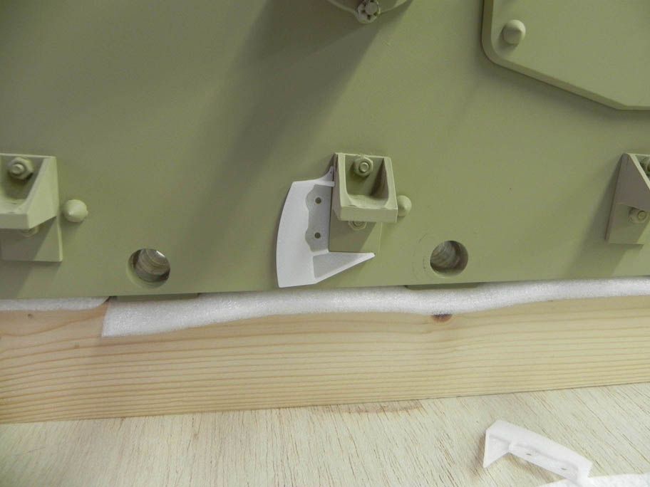
Below is another photo of the Suspension Guides, the grey one has had some filler applied to the blade and a couple of nuts have been place on to show how it will look when fixed to the hull. I intend to bond it and also use the two nuts to hold it on. The curved blade geometry is different to any of the book drawings, as the blade curve has been modified to suit the standard Suspension Arm placement and range of movement. Some others have moved the Bump Stops to a lower, more accurate, placement. However the area where I can use my Panzer III is quite rough and I don't want to limit the Suspension Arm movement. After using the Panzer III for a while I might investigate the amount of movement, before the Suspension Arms hit the Bump Stops, and then maybe lower the Bump Stops.
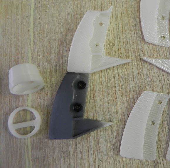
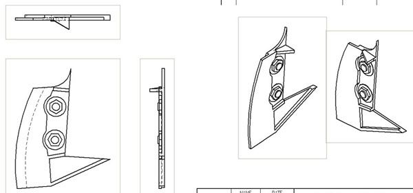
I also did a 3D CAD model of the Tail Light, which came out quite well. The front snaps on, so I can fit a working light inside. The Light is in the photograph above and the 3D model is below.
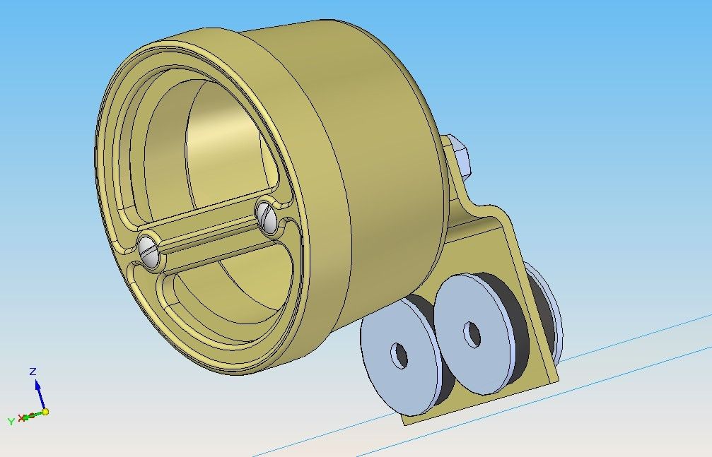


I also did a 3D CAD model of the Tail Light, which came out quite well. The front snaps on, so I can fit a working light inside. The Light is in the photograph above and the 3D model is below.

Last edited by Sarah Frazer on Sat Oct 24, 2015 1:00 am, edited 3 times in total.
'I reject your reality and substitute my own'
-
Adrian Harris

- Posts: 4919
- Joined: Thu Jul 12, 2007 10:46 pm
- Location: Berkshire (UK)
- Has liked: 1211 times
- Been liked: 1386 times
Re: Sarah's Panzer III build
Nice looking parts Sarah
Interested to see you're keeping the "stock" suspension travel.
Do you think there's any danger that the arm will detach from the guide when it's unloaded ?
Adrian.
Interested to see you're keeping the "stock" suspension travel.
Do you think there's any danger that the arm will detach from the guide when it's unloaded ?
Adrian.
Contact me at sales@armortekaddict.uk for details of my smoker fan control module
-
Sarah Frazer
- Posts: 202
- Joined: Sat Oct 17, 2009 8:12 am
- Location: Bristol
- Been liked: 2 times
Re: Sarah's Panzer III build
Hi Adrian,
I have left enough room for the guide blade on the suspension arm itself, but at this stage I'm not sure i am going to fit it, the same as Stephen. It is worth fitting it on the hull side as this is the most visible, without any problems of what would happen when you get debris in the gap between the fixed and moving guides. Additionally I can leave a greater clearance, so there should not be any problems if it does get unloaded.
I did experiment with different versions of suspension arms and if I do put the guide blade on the suspension arms, I will cheat a bit and only have it sweeping over the front and side of the fixed part, rather than going to the front, side and the back of the fixed suspension guide. Also the guide blade on the suspension arm I will do in metal, the suspension guide on the hull being 3D printed in a polymer. If anything does go wrong and it gets damaged then a 3D printed suspension guide is less than £4 and can easily be replaced.
If I do decide to move the Bump Stop lower, when I have a bit more running experience with the Panzer III, then it's just a case of changing the blade geometry and getting another set 3D printed.
Regards,
Sarah
'I reject your reality and substitute my own'
-
Luc De Weirdt

- Posts: 128
- Joined: Wed Aug 17, 2011 5:38 pm
- Location: Belgium
- Been liked: 16 times
- Contact:
Re: Sarah's Panzer III build
Hi Sarah,
It's the first time I take a peek at your project and I must say that I'm very impressed.
I'm sure that when this panzer is finished it's gonna be a real eye cather.
Gr. Luc
It's the first time I take a peek at your project and I must say that I'm very impressed.
I'm sure that when this panzer is finished it's gonna be a real eye cather.
Gr. Luc
"We are going to have peace even if we have to fight for it" - Dwight D. Eisenhower.
-
Sarah Frazer
- Posts: 202
- Joined: Sat Oct 17, 2009 8:12 am
- Location: Bristol
- Been liked: 2 times
Re: Sarah's Panzer III build
Hi,
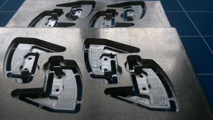
I've been updating some drawings for a small machine shop and managed to blag a bit of CNC time. So I have remade the Panzer III Suspension Guides I originally had 3D Printed in aluminium. They are an exact copy of the 3D printed ones and they took forever to machine, well not the five minutes I was expecting!
I'm still not sure about making the blade part that fits to the suspension arm, as it looks as though it is mostly obscured by the wheels. I'll have a good look at the panzer III at Bovington this weekend.
Sarah
I've been updating some drawings for a small machine shop and managed to blag a bit of CNC time. So I have remade the Panzer III Suspension Guides I originally had 3D Printed in aluminium. They are an exact copy of the 3D printed ones and they took forever to machine, well not the five minutes I was expecting!

I'm still not sure about making the blade part that fits to the suspension arm, as it looks as though it is mostly obscured by the wheels. I'll have a good look at the panzer III at Bovington this weekend.
Sarah
'I reject your reality and substitute my own'