Mike, what can I say? Simply outstanding work, superb, magnifique!!!!
For myself put me down for a complete M3 set cut, folded and drilled ready to go. As you say this would save a CONSIDERABLE amount of time, they would fit perfectly and there would be no waste. Perfection costs, but in this case its definitely worth it.
Before you tool up I have a couple of comments to assist authenticity.
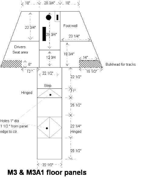
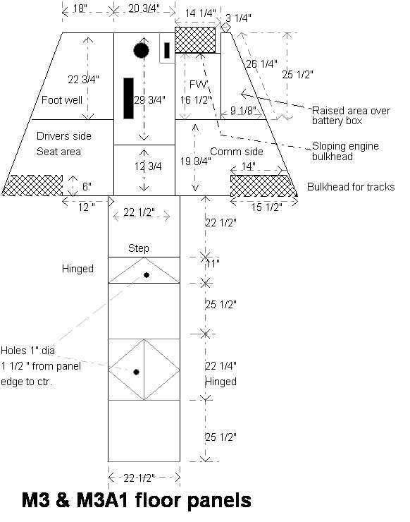
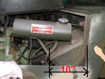
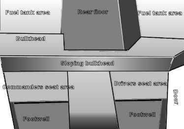
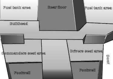
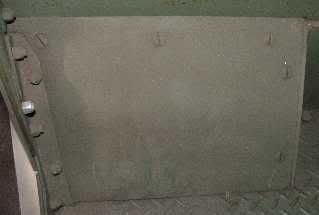
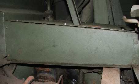
The bulkheads over the tracks (behind the front seats) are steel plate, not checkerplate as shown in this photo.
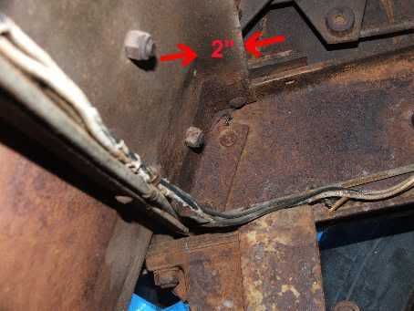
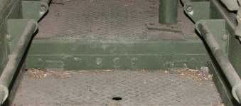
The step in the rear floor is flat plate, not checkerplate as shown here.
The clutch and brake pedals have this pattern.
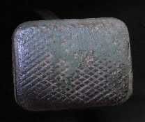
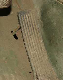
The throttle pedal has this pattern.
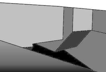
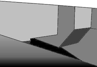
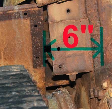
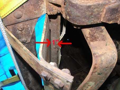
Can't remember on the model, but the real front center floor plate is at an angle as shown here. This would make the middle slighly longer overall when compared with the two outer sections.
Hope this helps Mike.
Its over to you guys now. Can someone copy their model floor sections or lend them to Mike for prototyping?
Cheers all!!!!