Tiger 066 Construction

Forum for discussion relating to the King Tiger
John Grima
Posts: 250
Joined: Sun Jul 15, 2007 2:54 pm
Location: USA
Been liked: 48 times
Contact:

Tiger 066 Construction

Post by John Grima »

Hello All, I have had the kit in storage for about a year and now that the M26 is out of the way I can finally start on this tank.

So far I have the tank's hull and turret bolted together.

Image

Image

Image

Image

The one plate in particular that impressed me the most is the front glacis plate. It's probably my favorite part of the build so far.

Image

Image

Image

Now that the hull is together I can add the welds and under hull detailing.

Image

Image

This model is going to be the heaviest model that I have ever built. The hull and turret, in it's current empty condition already weighs over 100lbs. Once the tank is up to the suspension I will have to move the tank out of the shop into another location that is easier for me to work on. If I don’t remove the model out of the shop before the suspension is added the tank will be too heavy to get it out of the shop.

Image

Image

Image.

Brian Leach
Posts: 363
Joined: Tue Nov 18, 2008 4:15 pm
Location: Auburn, Wa USA
Been liked: 3 times

Post by Brian Leach »

John,

Nice pictures.

I have a question for Mark and Gill:

When you cut the hull parts such as the glacis, do you use a water jet, or do you you mill them down from a rough cut piece of Al?

Thanks,
Brian
Brian


Reasonable people act reasonably!

John Grima
Posts: 250
Joined: Sun Jul 15, 2007 2:54 pm
Location: USA
Been liked: 48 times
Contact:

Post by John Grima »

It has been a little while since I had any updates, but I have been working on the model in between processing orders and working on another non 1/6th scale project.

Since my last post I have been working on the tank's lower hull, and getting it ready for the suspension, and a coat of primer.

Image

The tanks lower hull seams were all cover up with sculpted epoxie weld beads.

Before

Image

Image

Image

Image

After

Image

Image

Image

Along with the welds I have been plugging up the bolt holes, and added the torch cut lines to the intersecting panels.

Image

Image

Image

Along the bottom portion of the tank I added several recessed torsion bar bolt details. These bolts are found on either side of the reverse side of the torsion bars.

Image

Image

On the tank's lower front portion the kit has four bolts that are used to mount the final drive hub to the tank's hull. On the real vehicle there are three counter sunken cap screws, rather than four surface bolts. To correct this I drilled recessed into the tank's hull for the new cap screw detail, and I drilled the recesses for the actual final drive mounts. When the final drives are installed the four bolts will be covered up with the body work, and the three cap screws will remain as detail only.

Image

To mount the final drive armored rings to the tank the kit wants you to use a hex bolt. The hex bolt head that remains on the surface is not found on the real vehicle. To correct this I replaced the hex bolt with a counter sunk allen bolt, A counter sunk recess was added to the tank's hull, after the armored ring is added the bolt will be covered up with putty. Welds will be added to this portion once all of the body work in this area is complete

Image

Image

When I got up to the bump stops I wanted to add more detail than what is found on the stock part.

Image

The bump stops are installed with cap screws, and the bump stop tops have a large cap screw protruding out of it.

Image

Image

Image

The stock bump stop has the overall shape and appearance of the real bump stop, but what was needed was to rework the bump stop frame, and re detail the bump stop top. To start on the bump stops sides I milled away a recess for the new bolts. A new recess was also milled into the bottom bolt hole replacing the counter sunk screw with the correct recessed hex screw.

Image

On the bump stop top to replace the cap screw I used a counter sunk hex bolt in it's place. to do this I had to add the counter sink divot to the bump stop top.

Image

The reason for the bump stop top is because I machined a resin detail disc that fits over the entire bump stop top. In the resin disc I cut out the recesses for the small resin hex bolt details. a rough cast texture was also added to the bump stop frame and bump stop rein detail top.

Image

Image

The real tank bump stop has more detail on them, which I could have added, but because this bump is not only for detail, but is designed to function I decided to leave the detail towards the top half only where damage is less likely to occur. In addition the top half will be the only part of this component that will be seen once the running gear and suspension are added.

Image

Image

I also machined out of aluminum two pointed caps that I have seen on the real King tiger's hull. There is only one per side and are both found under one of the bump stops. I will be adding these parts to the product line.

Image

Image

Image

On the tank's interior I have add the motor mounts. Both motor mounts needed a small amount of material removed for a better fit with the motors.

Image

For the left hand motor mount I borrowed Dale's modification technique and milled in a recess into the motor mount so once fitted I can fit the torsion bar tension screw

Image

Image

The motors can now be installed.

Image

The tank's final dricves have been added. They were installed as is with no added mods.

Image

Image

Image

Image

One nice new addition that I liked was the gasket. A smear of marine grease and the mounts were added to the tank.

Image

After I complete some body work I will be able to start on the torsion bar suspension.

User avatar
Armortek
Site Admin
Posts: 2899
Joined: Tue Jul 10, 2007 10:30 am
Location: Winchester, England
Been liked: 3501 times

Post by Armortek »

Hi Brian

We don't use water jet cutting at all any more. All the steel sheet parts are laser cut. The upper limit on commercial laser cutting of aluminium sheet is 12mm thick. Any parts that thicker than this, we mill from sawn billets of ally plate.

Regards
Mark
Armortek

Tim Bowman
Posts: 1762
Joined: Fri Jul 13, 2007 4:53 am
Location: Northern California
Been liked: 177 times
Contact:

Post by Tim Bowman »

Hi John

After watching you beautiful M26 come together, I can only imagine how nice this tiger II will be.

Looking forward to each post.
Kind regards
Tim
"So long as one isn't carrying one's head under one's arm, things aren't too bad." – Erwin Rommel

John Grima
Posts: 250
Joined: Sun Jul 15, 2007 2:54 pm
Location: USA
Been liked: 48 times
Contact:

Post by John Grima »

I have made more progress on the model.

Image

The tank's lower hull has been primed. a coat of primer was also added to the interior.

Image

Image

Image

Image

Image

The body work was complete on the lower front portion, and on the motor mount rotors, that would have been seen behind the final drives. The six Allen cap screws will be added next.

Image

Image

The tank's idler mounts were added.

Image

Image

Image

Image

Image

Image

Along with the idler mounts the torsion bar suspension has also been added.
One nice addition that I like was the addition of brass bushings for the swing arms, and the addition of rubber O rings.

Image

Image

Image

One modification that I made to the swing arms was to lock the axels to the swing arms. I learned to do this mod after I built their tiger I and noticed that some of the axels unscrewed themselves. To lock the axels I drilled a small hole through the swing arm and the axel. A brass rod is then inserted into the hole and is then expanded and ground flush.

Image

Image

Image

Image

Image

Image

After the rods get painted, they get a smear of grease and are then installed into the tank.

Image

Image

Image

Image

Image

The tank is now ready for the running gear. Before I start on the running gear the tank will have to be moved out of the shop because of the weight. More progress to follow.

John Grima
Posts: 250
Joined: Sun Jul 15, 2007 2:54 pm
Location: USA
Been liked: 48 times
Contact:

Post by John Grima »

I have made some progress on the tank. The base dark yellow has been applied to lower hull and the wheels. The Hull was then moved to its new location where the remainder of the tank's construction will be completed. The tank will be built on a high capacity hydraulic lift dolly.

Image

Image

Image

Image

Image

Image

When the base coat was applied the axels were covered with masking tape, once the paint dried the tape was removed. After a smear of grease the wheels were added.

Image

For the wheels the kit supplied wheels are nicely done, but needed a few mods to increase their detail.

Image

Image

Image

Image

The hub portion of the wheel is one CNCed aluminum turning. On the real hub the hub is divided in three segments. These segments were added to the kit hub.

Image

The fasteners that are used to assemble the wheels are all slot screws, which are attached with hex nuts on the hub surface.

On the real tank the hubs have half of the fasteners reversed. This means that some of the bolts have their bolt heads on the out side of the wheel, and the other bolts are on the inside and their hex nuts are exposed on the exterior of the wheel.

On the model I first added the bolts that have thier hex nuts exposed in the positions that they are exposed on the real tank.

Image

For the reversed hex bolt details the mod that I had to make was I first bolted the hex bolts to the hubs like the other screws. I then ground off the extra threading overhanging off of the nut. I then soldered the nut to the bolt. This makes the nut look like a hex bolt. This was done because the bolt itself is a slot screw and not a hex bolt, and I had trouble locating a hex bolt of this size and length.

The overhang threading on the other rim bolts were also trimmed.

Image

Image

The wheels have been added to the tank. The tanks wheels hub caps will be added after a few more mods have been added. These will be next along with the addition of the sprockets and the idlers.

Steve Norris
Posts: 1229
Joined: Thu Jul 12, 2007 11:42 am
Location: Manchester
Has liked: 8 times
Been liked: 697 times

Post by Steve Norris »

John
Great looking build as always.
I noticed that on one of the hub segments there was only 4 bolt holes were the others had 5, If it is the same set up as my late Tiger 1 there should be 5 bolts in each segment ( it may be worth checking out before you get to far with build).
Keep up the great work
Steve

John Grima
Posts: 250
Joined: Sun Jul 15, 2007 2:54 pm
Location: USA
Been liked: 48 times
Contact:

Post by John Grima »

Thanks Steve, I was unsure about the missing hole, but after looking at the images that I took of the aberdeen jagdtiger I now see the extra bolt. Luckily I ran out of locktite last night so the wheels have not been locked on the tank yet, so I will be able to add the missing bolts today.

Image

Image

David Da Costa
Posts: 241
Joined: Wed Nov 25, 2009 4:51 pm
Location: California
Contact:

Post by David Da Costa »

Great thread John!

My KT is still waiting in my storeroom to get built, but it keeps getting pushed to the end of the construction line (now after the Comet and new Ultimate Panther Kit in 2011), but I am looking forward to building it.

Regards

David

John Grima
Posts: 250
Joined: Sun Jul 15, 2007 2:54 pm
Location: USA
Been liked: 48 times
Contact:

Post by John Grima »

Thanks David, These tanks are a lot of fun to build and I am having a blast.

The suspension is now mostly complete.

Image

I added the missing bolt on all of the road wheels.

Image

All of these bolts are secured with locktite.

Image

Image

Image

The hub caps were also installed. These parts need some modifications.

The stock armortek hub caps are all turned aluminum and have the correct shape and size.

Image

Image

Image

On the real vehicle the stems of the hub caps are casted. The cap itself is a flange that bolts to the stem. The cap is fastened to the stem with several hex bolts around the rim that bolt into a casted steel lump that is casted into the stem. I used the above image that I took from the Aberdeen Jagdtiger for reference.

On the armotek piece the cap is one with the stem and the flange seem is missing. These seems were added to all of the caps on my lathe.

Cast texture was then added to the stems. There are cast numbers on the real vehicle on these parts, but I didn't add them because of the location of the stems the road wheels could hit the stems on a bump and knock the cast numbers off.

The lumps where the bolts from the cap thread into the stem were also added. these were all sculpted into each of the stems with epoxy. This was the most time consuming part of the mod, but give the tank's road wheels a nice touch.

Image

On the face of the hub cap there are several bolts that mount the hub cap plate to the stem. There are also securing plates to keep the bolts from getting loose like on the road wheels. The securing plates were not supplied with the kit, so I made the bolt detail with securing plates out of resin. I also used resin hex bolt heads for the center grease fitting bolt. The resin casting saved a lot of time with having to create every securing plate out of metal by hand. In addition the resin casting work well for this application because in my experience this area is not hit very often when the tank is driving.

Image

Image

After a shot of primer they were installed to the tank.

Image

Image

To instal the parts they simply get screw into the wheel plate. This was another nice touch

Image

Image

The completed hubs

Image

Image

Lastly the tank's Idlers were installed. These idlers were mounted to the tank OOB with no mods needed.

Image

Image

I have added the turned suspension caps and the resin hub cap details to the product line. http://eastcoastarmory.com/germanparts.htm

I'm currently working on the tank's sprockets. More info to come.

John Grima
Posts: 250
Joined: Sun Jul 15, 2007 2:54 pm
Location: USA
Been liked: 48 times
Contact:

Post by John Grima »

Thanks Nick, I always post in this format when I'm building my 1/6th scale tanks.

I have made progress on the tank's sprockets and drive train.

Image

The tank's sprockets are made out of CNCed Aluminum and the bell housing is separate from the teeth rings like the real vehicle. The sprockets mount to the drive axel via a taper lock. The sprockets also come with PE fastener locks.

Image

Image

Image

Image

Image

Overall the sprockets are nicely done, but a few mods were needed to improve on the sprockets detailing. The sprockets have several tooling marks where the bell housing curves.

Image

Image

Image

These marks were easily ground off with a dremel using a sanding drum.

Image

Image

Image

Image

Image

After the tool marks were removed cast texture was added to the entire bell housing of the sprocket. Cast numbers were also added to the bell housing. Epoxie sculpt was added to the spokes because on the real vehicle the spokes stand slightly above the center hub. This bit of detail will be more noticeable once the center hub is mounted to the sprocket.

Image

Image

The teeth rings were a very tight snug fit on to the sprocket, to help with the installation I sanded the inner ring down very slightly with a large sanding drum that was mounted in my drill press.

Image

To mount on the sprocket rings the kit wants you to use the same slot screws that were used on the road wheels. The slot screw heads were positioned on the inside of the sprocket and the hex bolt would be positioned on the exterior face of the sprocket ring. On the real tank the bolts are inverted, which means the bolt face is on the exterior and the nut is on the inner portion. In stead of the slot screws I used M3 X 12 hex bolts and nuts. To do this I had to slightly enlarge the holes on the sprocket bell housing, the teeth ring, and the PE fastener retainers.

Image

Image

Image

A small length of track was assembled and was used as a timing jig to make sure the sprocket teeth align perfectly with the track.

Image

Image

One of the sprockets is complete and has been installed to the tank. The other sprocket is still going through it's finishing touches.

Image

To install the sprocket with the taper lock the instructions are listed in the armortek instruction booklet and they work very well on my other armotek tanks.

Image

Image

Image

The same length of track that I used before as a timing jig was also used to adjust the placement of the sprocket on the axel.

Image

Image

In addition to the sprockets I have also mounted the tanks very large and heavy drive motors. These motors come pre assembled with the small drive gear and are simply bolted onto the motor mounts.

Image

Image

Image

I have also started on assembling the track. The track links are all cast aluminum alloy. They come pre drilled and are nicely scaled and detailed. The track is held together by a single pin. The newer generation armortek tank tracks are locked to the link by the use of a miniature cotter pin and retaining ring like the actual tank. Both the track pin and the retaining ring are pre drilled.

Image

Image

Image

Image

Image

The next bit of detail that needs to be added to the sprockets is the center hub detail. This will be complete with the next update. More to come soon.

John Grima
Posts: 250
Joined: Sun Jul 15, 2007 2:54 pm
Location: USA
Been liked: 48 times
Contact:

Post by John Grima »

It has been over a week since my last update but I have made more head way on the tank.

Image

Image

The other sprocket was completed and installed,

Image

Image

Image

The six allen screw bolt heads were added to the lower front, this completes the lower front portion of the tank.

Image

I'm now focusing on the tank's rear wall detailing. The kit supplies you with most of the details. Some like the idler tension cover caps and the engine starter caps were added as is, with no added detailing.

Image

Image

Image

Image

The tank's kit supplied exhausts come with very basic detailing and left an area which I saw room for improvement. The kit supplied exhausts each comprises of two CNC aluminum parts and one copper tube. The whole exhaust is then covered by an all aluminum CNC armored cover. The exhaust stacks and bases are hollow which allows a smoke unit to be installed.

Image

Image

Image

Image

To re detail the exhausts would have required too much work, instead I decided to fabricate new exhausts and to cast them in resin. These new exhausts have a more accurate appearance and do spice the exposed exhausts up a bit.

Image

Image

Image

Image

The exhausts are a solid resin casting, but I will be making my tank with a smoke generator, so the solid exhausts stacks were hollowed out. To do this I simply drilled a hole down the top of the exhaust base, and a connecting hole towards the exhausts stack rear.

Image

Image

For the exhausts pipes I used the stock armortek copper pipes. The pipes themselves are nicely shaped out of the box. To make them fit my resin exhausts bases I machined an adaptor tube out of a length of PVC tube.

Image

Image

The pipe's thickness is slightly too thick, so I thinned the walls on the end that is exposed with a dremel sanding drum. A small steel support rod was then soldered in the opening, as I have seen this on the actual vehicles. These stacks have been added to the product line in two variations, One as a complete set with my own resin solid exhausts pipes designed more for static king tigers, The other with just the exhausts bases and the copper pipe adaptor for the armortek RC King tigers with smoke generators.

http://eastcoastarmory.com/germanparts.htm

Image

Image

The hollow exhausts were then ready for installation.

Image

Image

Image

before I installed the stacks a small amount of silicone was added around the center exhaust hole. This hole is to give me an air tight seal which will keep any exhaust smoke from seeping out between the gaps.

Image

Image

Image

Image

The kit supplied exhaust covers are all CNCed aluminum and also appear to have the correct basic shape and appearance.

Image

Image

What was added to the exhausts covers was some cast texture, and a set of my metal armored exhaust lift bolts.

Image

Image

Image

Image

These were then installed to the tank with no problems

Image

Image

Now that the exhausts have been added all that remains to finish the exhausts is the crank started guide. This descends off of the right hand exhaust cover, and will have to be all scratch built. Once complete I can then finish off the remaining rear wall details.

On the tank's interior I have assembled the kit supplied electronics mounting tray. This tray will hole the batteries, smoke generator and other electronics. More Info to follow

Image

John Grima
Posts: 250
Joined: Sun Jul 15, 2007 2:54 pm
Location: USA
Been liked: 48 times
Contact:

Post by John Grima »

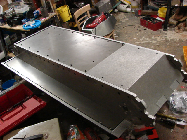
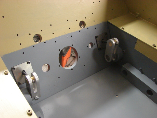
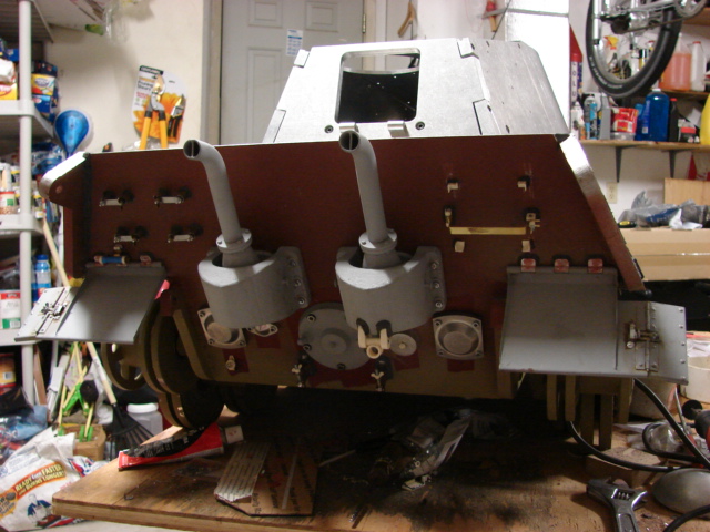
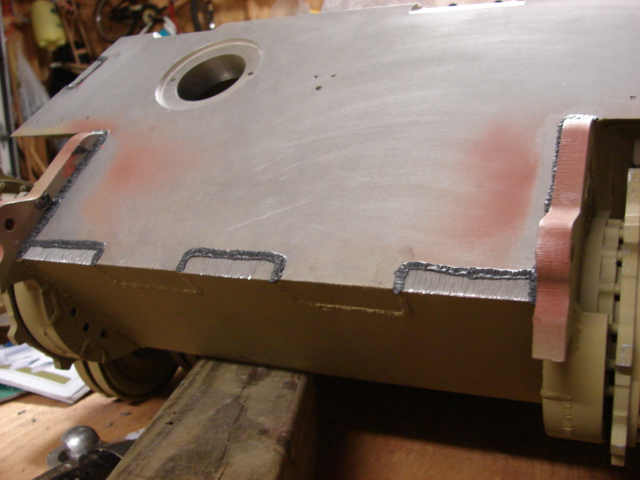
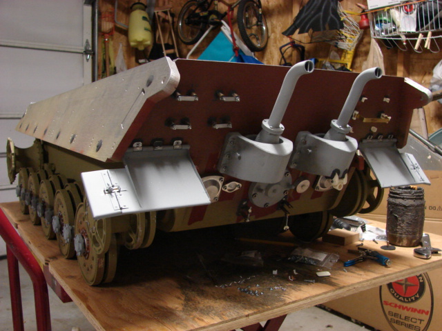
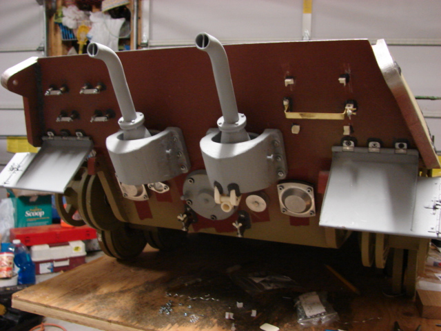
I have completed 96% of the rear wall detailing.

Image

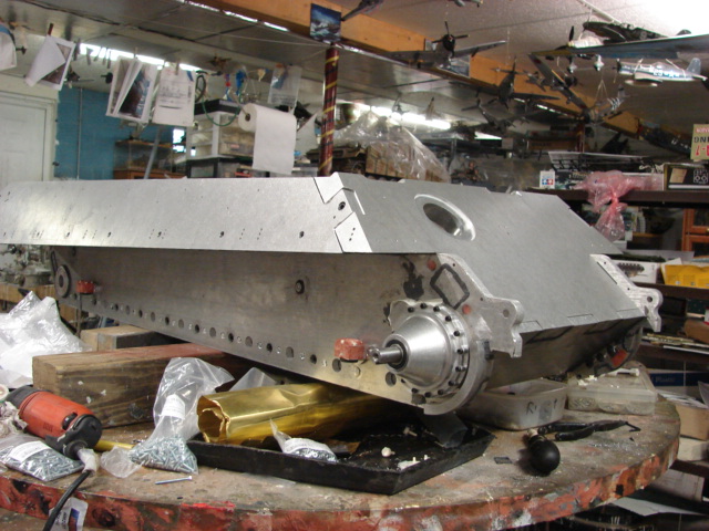
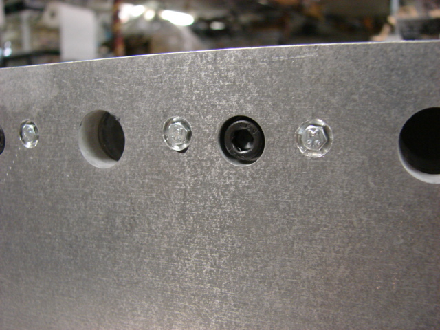
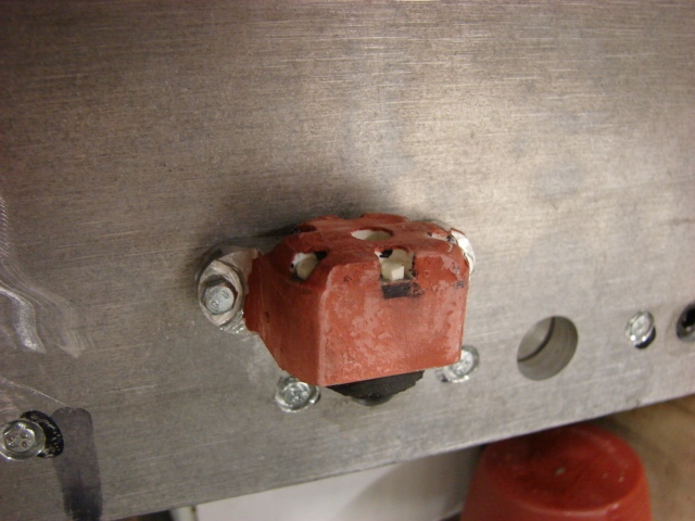
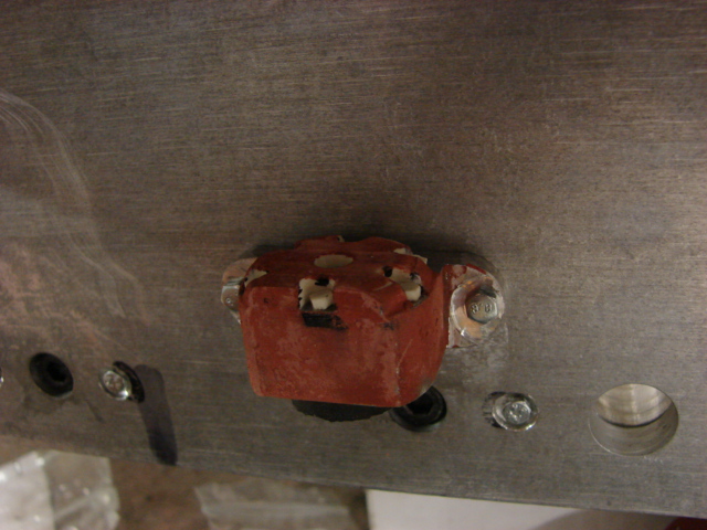
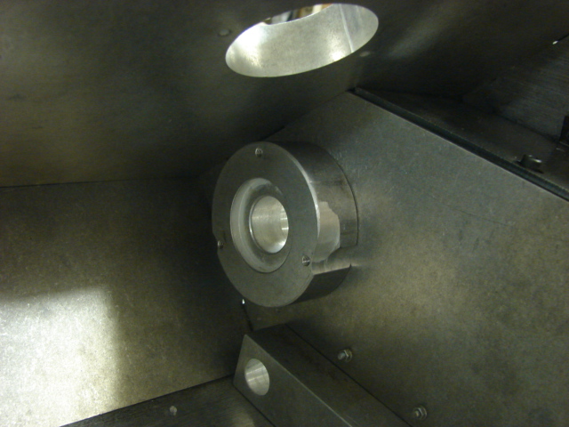
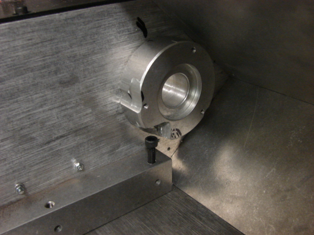
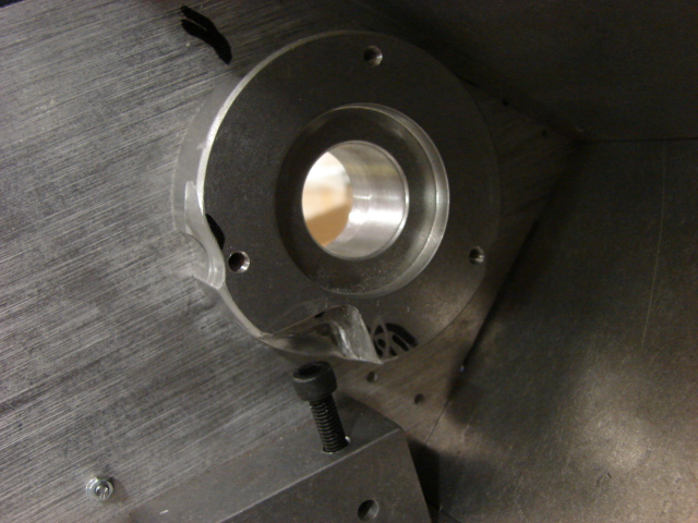
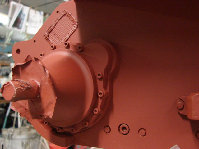
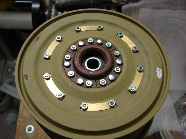
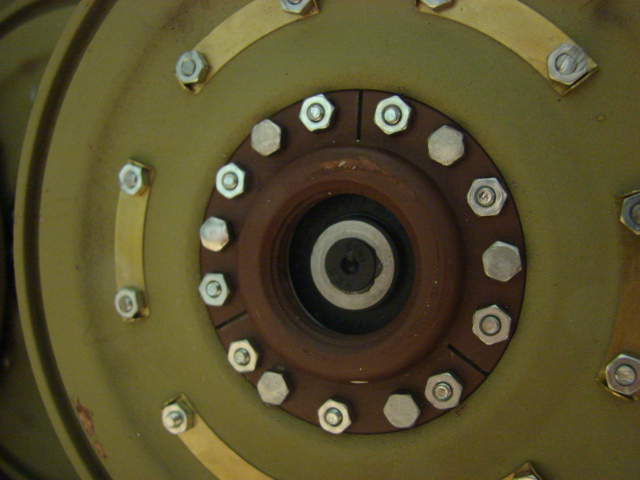
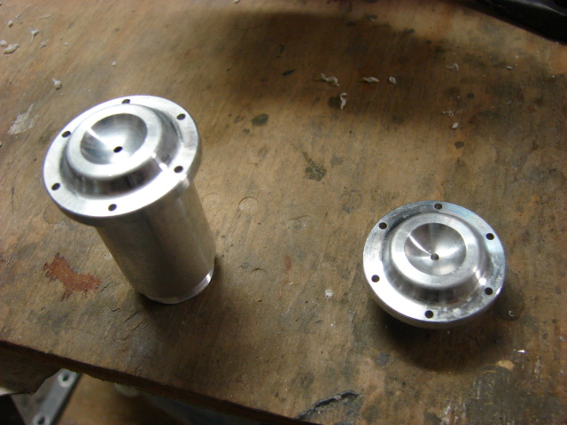
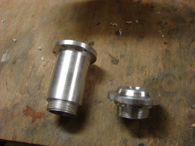
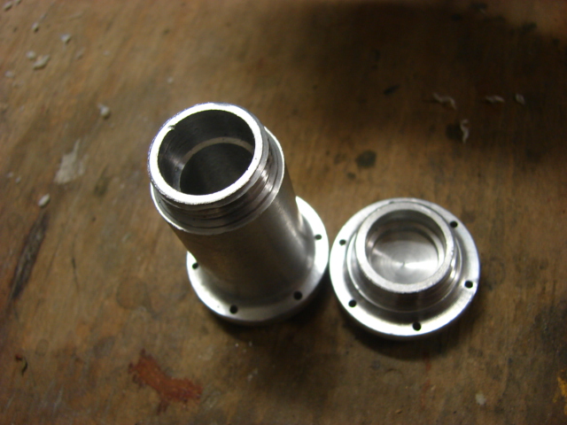
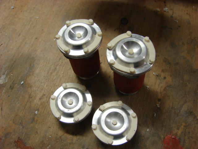
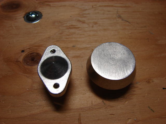
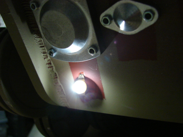
The tank's rear engine access hatch / engine started was reworked and added.

Image

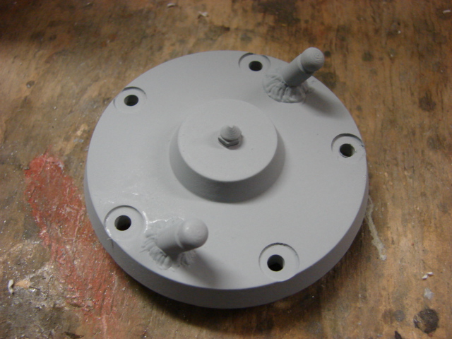
The kit supplied piece was made of CNCed turned aluminum and is the correct size and shape.

Image

Image

Image

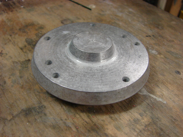
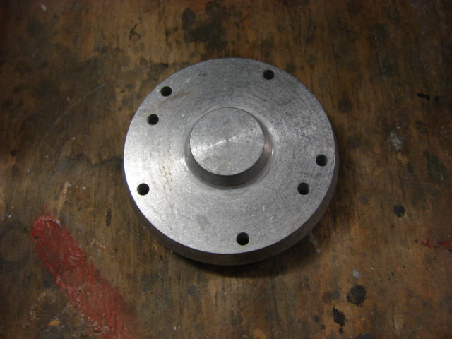
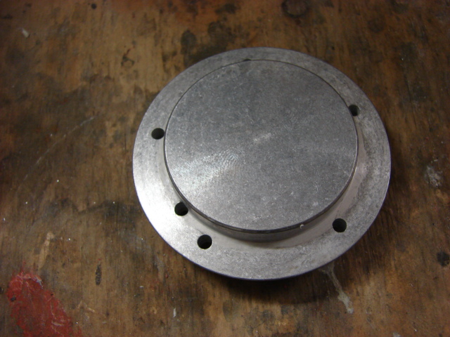
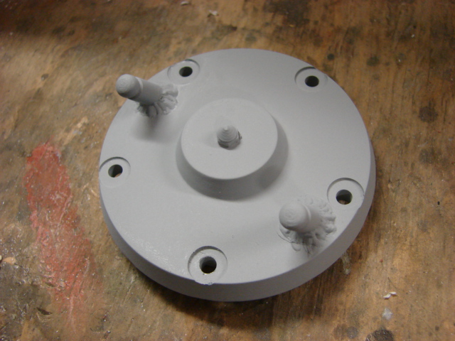
All that was needed to improve the part was I milled recessed divots into each of the locations that the mounting nuts are located, I added a resin Acorn nut to the center of the access hub, and I added two resin cold weather starter electrode nubs that was from my Tiger I cold weather starter kit.

Image

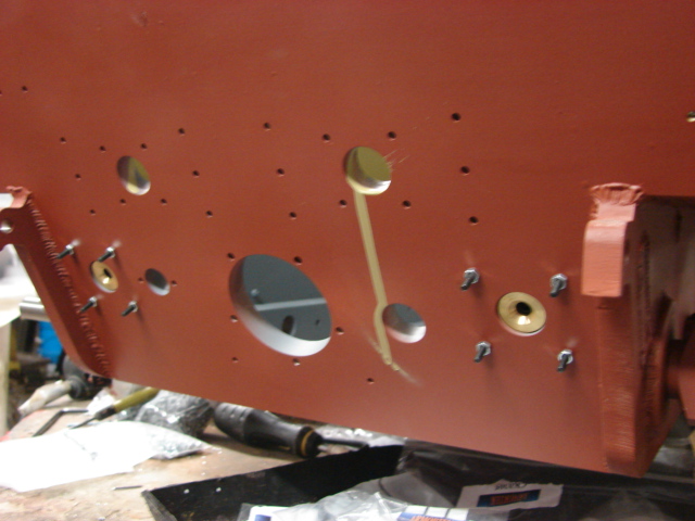
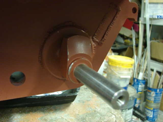
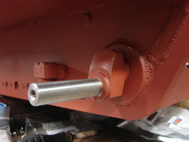
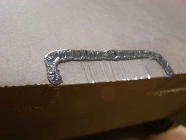
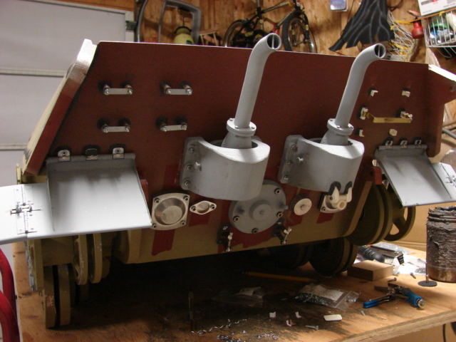
The tank's tow hook swing mounts were added. These mounts are nicely done out of the box and the only mods that were added were the weld beads. The kit supplies you with cast bronze wing nuts that thread onto the exposed threaded shaft. The kit also supplies you with two cast brass tow hooks. These appear to need no further mods and will be added once the tank is painted.

Image

Image

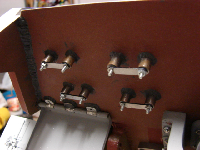
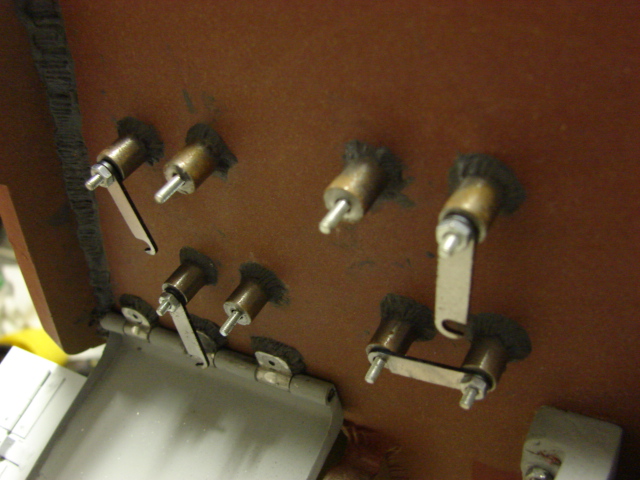
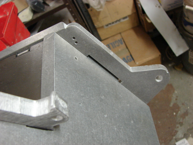
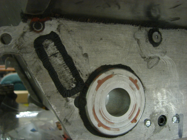
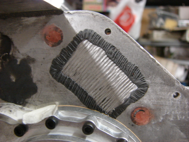
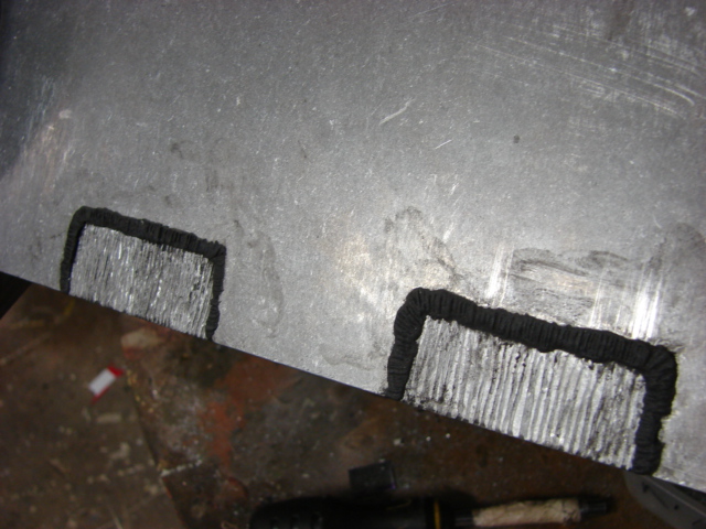
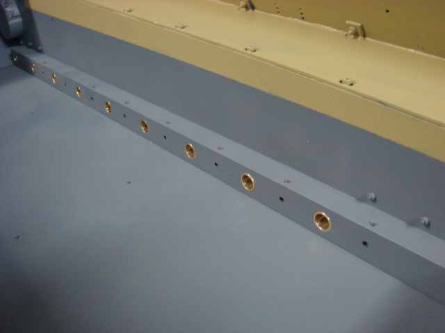
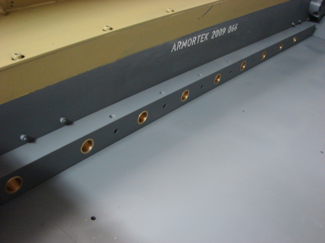
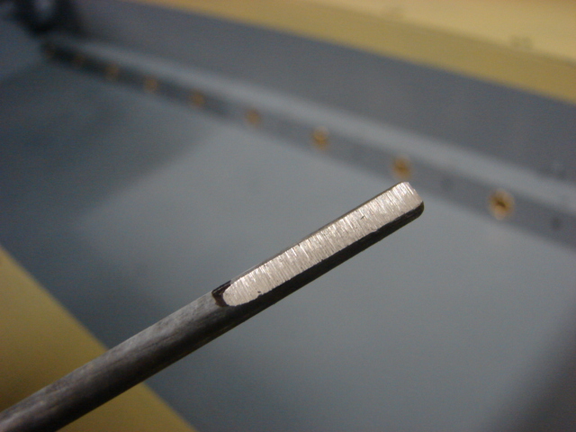
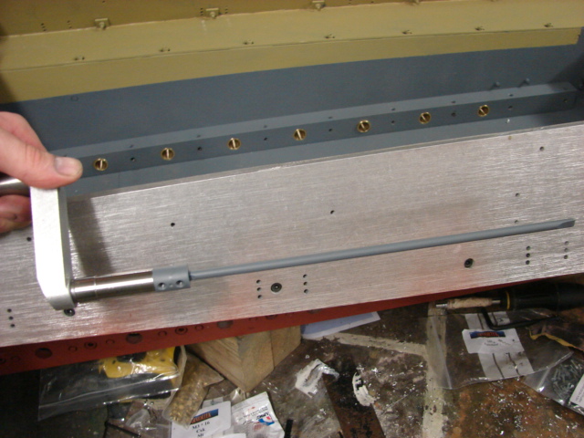
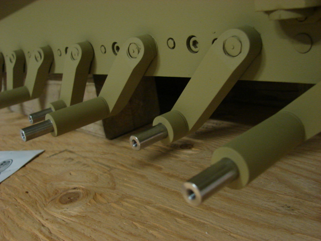
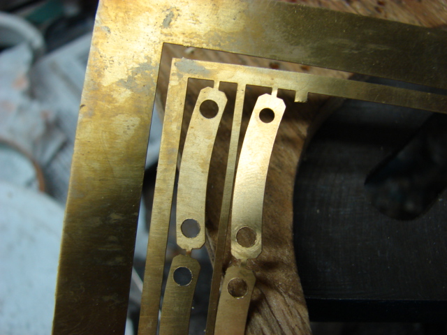
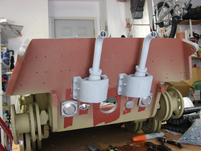
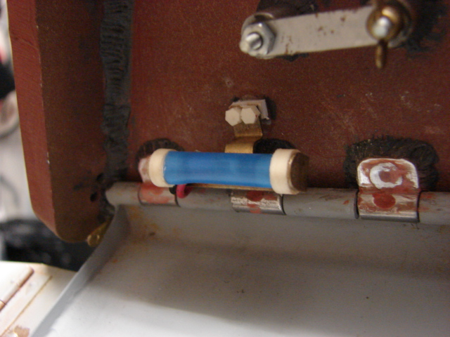
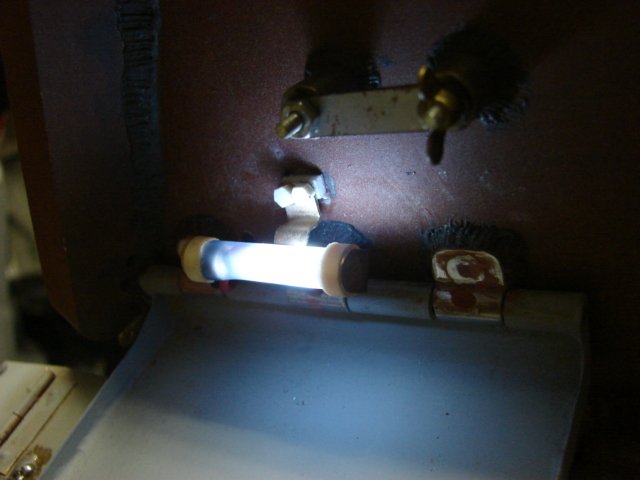
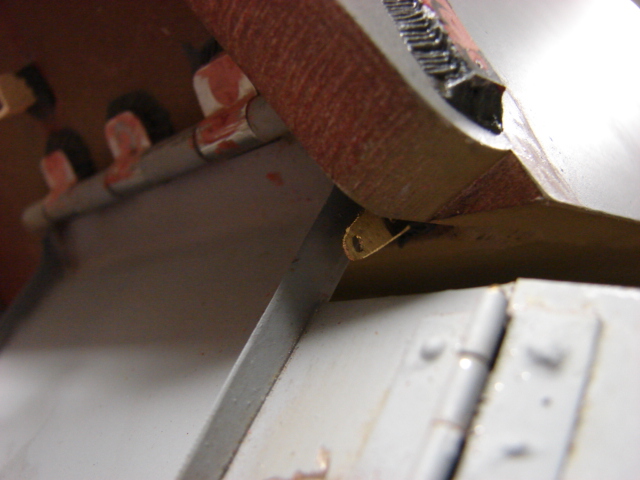
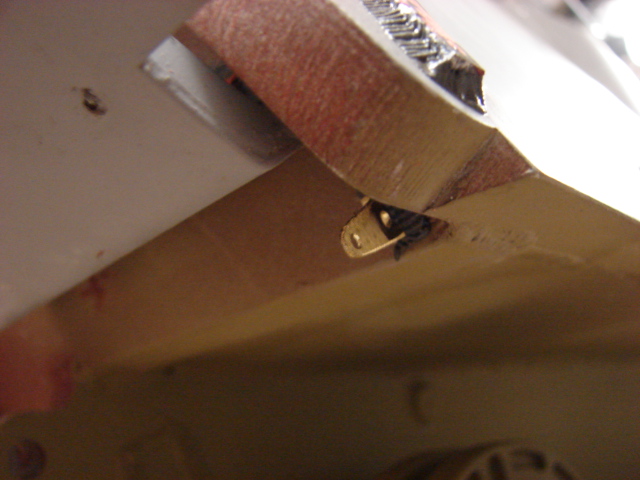
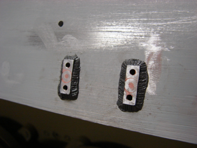
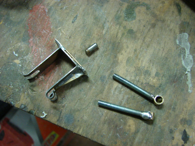
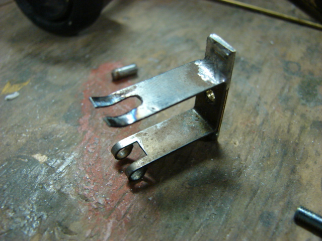
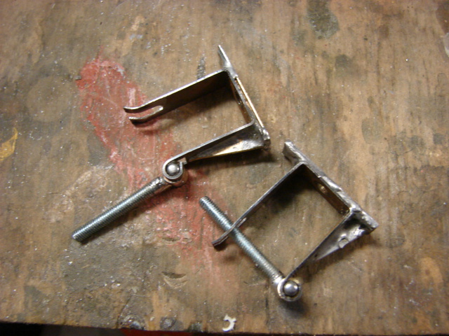
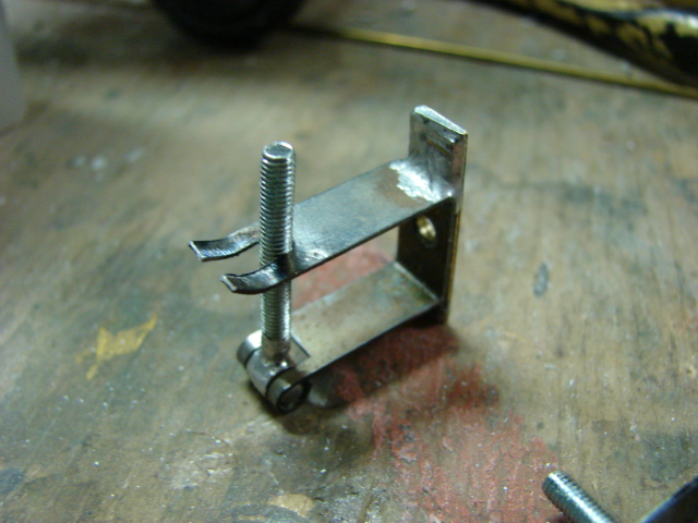
The tank's jack mounts were added. The kit supplied mounts are made out of two laser cut and pre shaped sheet steel strips. The kit supplied mounts are made to swing open. On the real tank the mounts are welded to a longer plate and have a bulkhead welded to the lower portion of the mount for more strength. On my component I made the bulk head and the longer base plate out of a brass strip that was then soldered onto the kit supplied jack mount.

Image

Image

Image

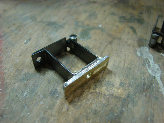
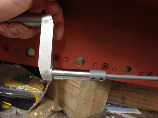
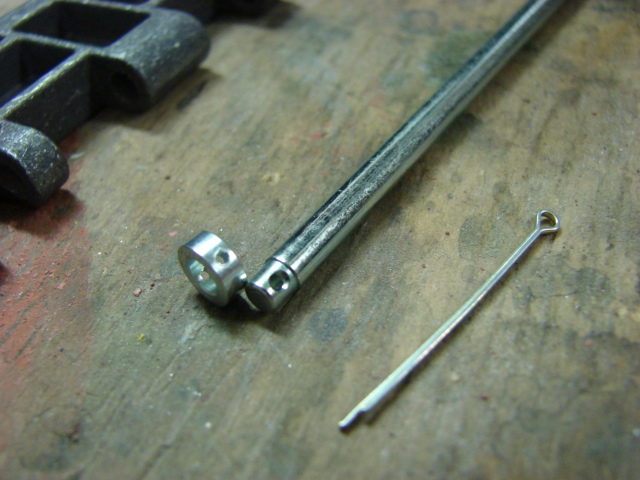
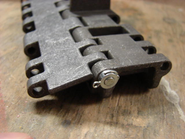
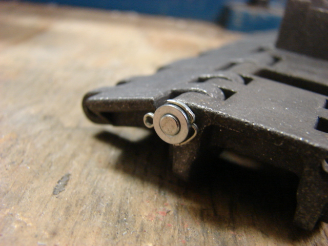
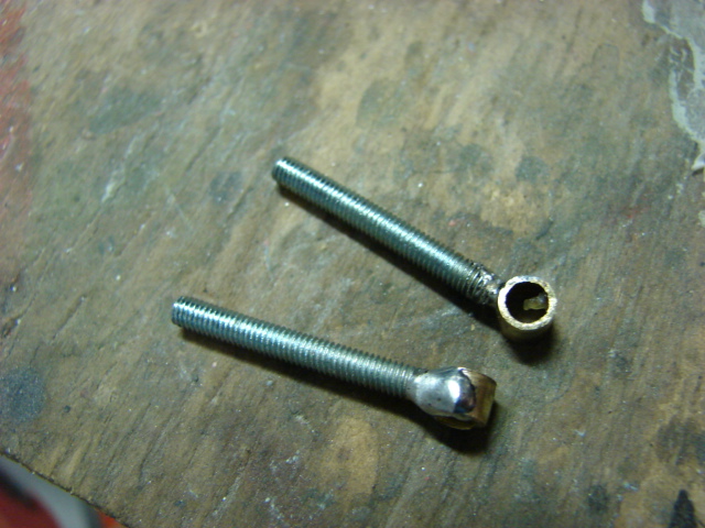
At first I was going to install the component with the kit supplied hinged gate, but after reviewing the real component I decided to rework the jack mounts further. To do this I removed the kit supplied gate and replaced it with a threaded rod that was soldered to a brass tube. The new rod swings in place where the old gate once went. The op portion of the jack mount was to be secured by a singe Allen screw and nut, this part of the mount was bent straight and a threaded shaft size notch was then cut into the now protruding steel. A resin wing nut will hold the unit together.

Image

Image

Image

Image

Image

Image

Image

As for the tank's Jack, the kit comes with an Armorpax Resin and metal King tiger Jack, which is an excellent bit of kit. This too will be added later.

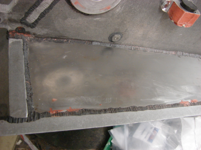
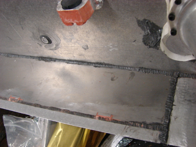
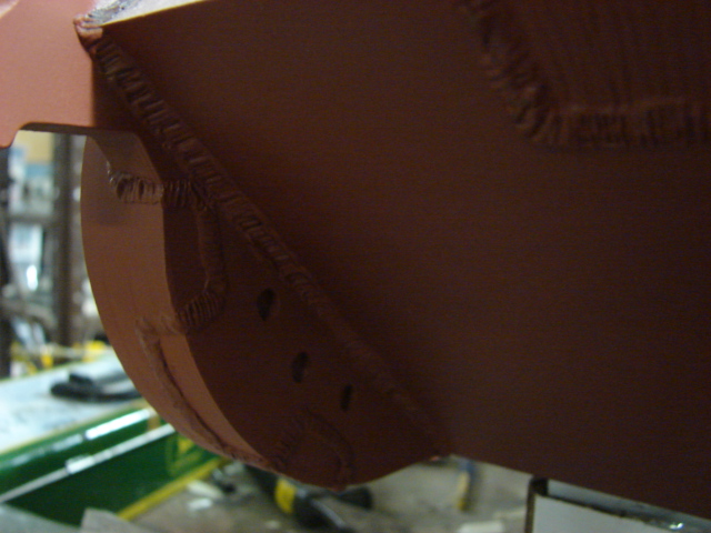
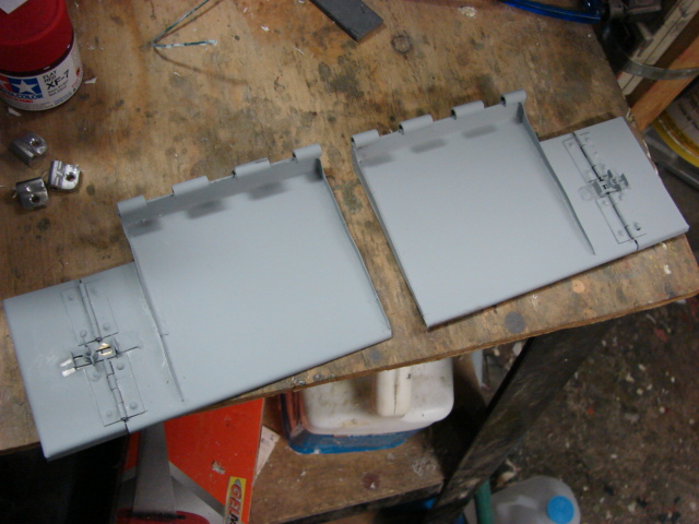
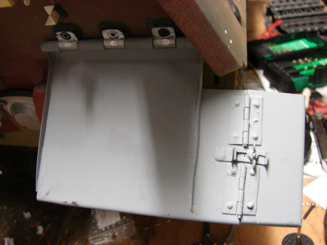
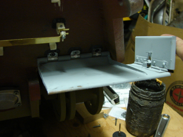
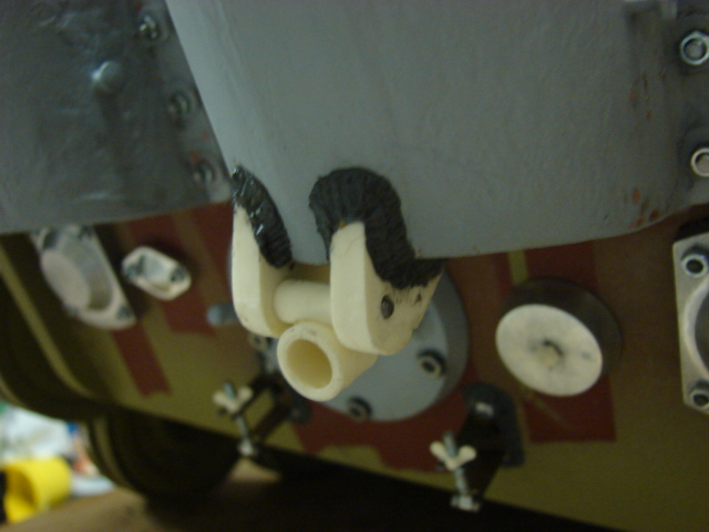
The tanks Rear mud flaps have also been assembled and installed.

Image

The kit supplied mud flaps are all made out of pre shaped laser cut sheet steel, brass hinges, copper rivets, and two machined aluminum one piece hinges.

Image

Image

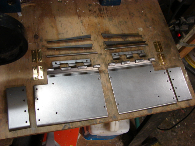
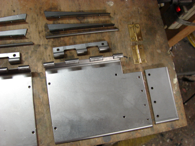
The kit supplied mud flap bulk heads were not used. New sheet steel bulk heads were fabricated and soldered to the mud flap in it's place. The original mounting holes for the kit supplied bulk heads were plugged up with solder and were sanded smooth.

Image

Image

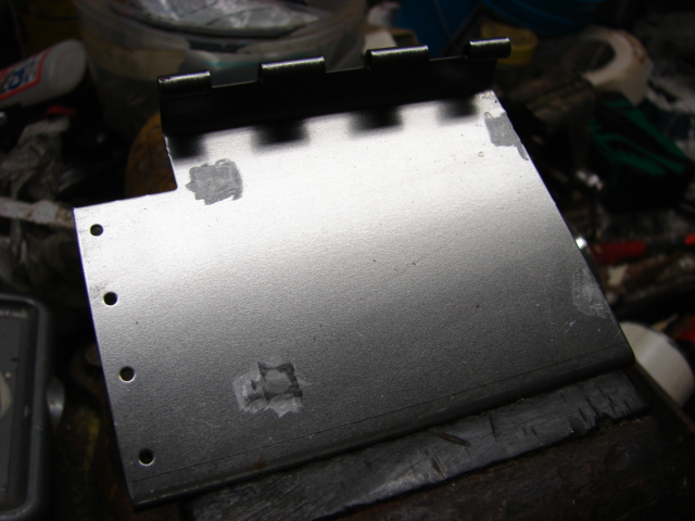
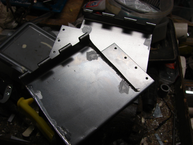
All of the hinges and copper components were soldered directly onto the mud flaps. The mud flap corner hinged section had it's adjustment plate detail added. These details were all scratch built out of brass. A resin wing nut adds the last bit of detail to the section.

Image

Image

Image

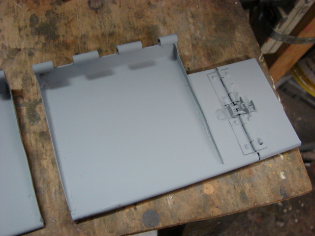
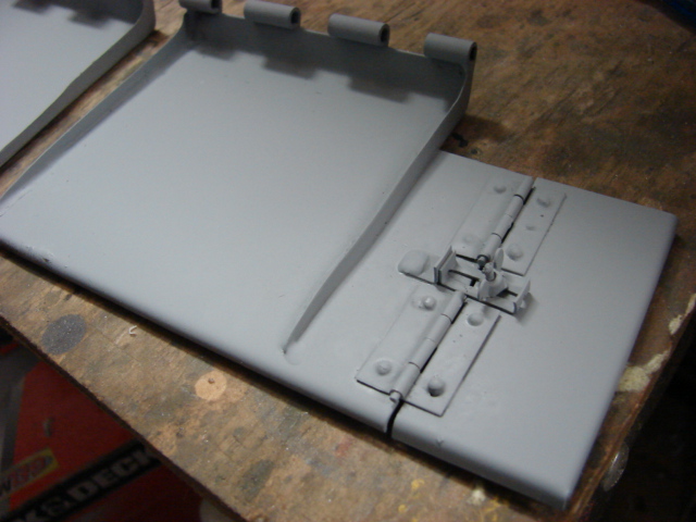
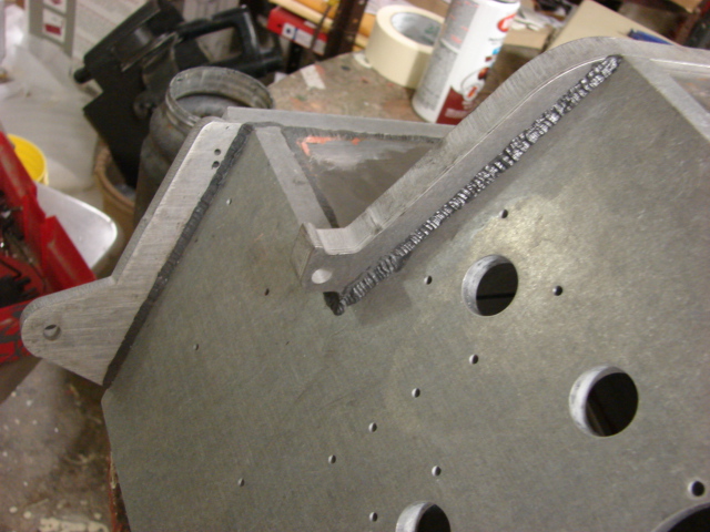
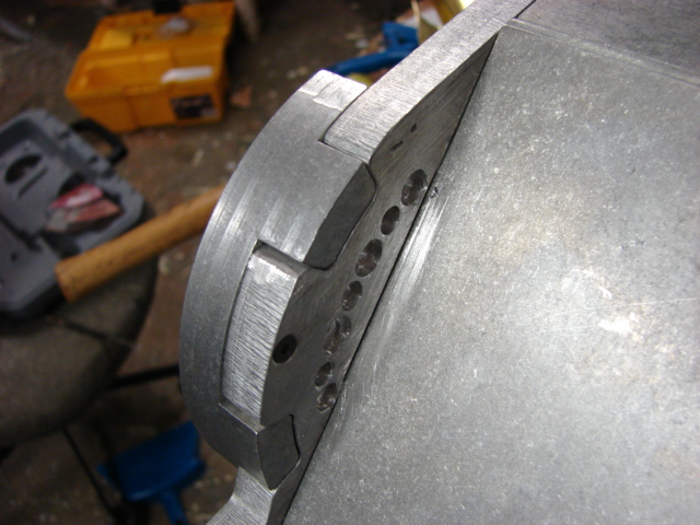
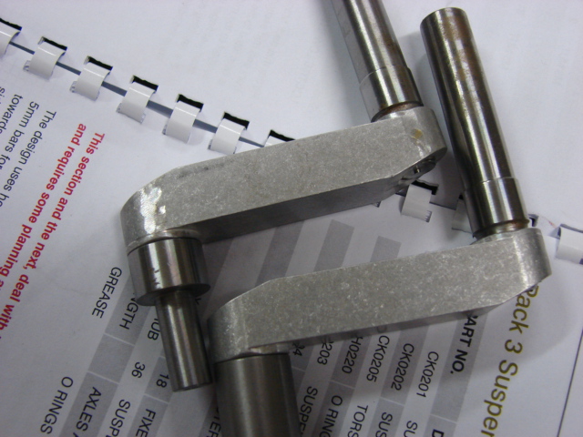
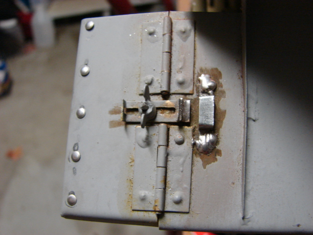
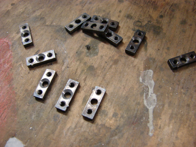
To complete the mud flaps, the one piece main hinge needed to be reworked.

Image

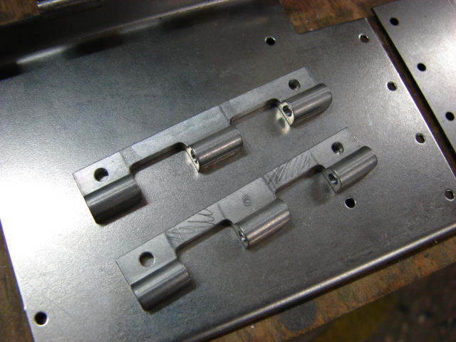
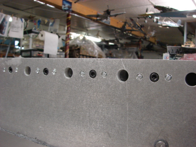
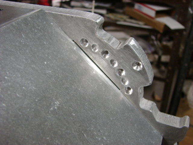
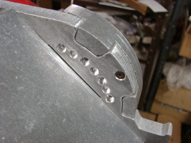
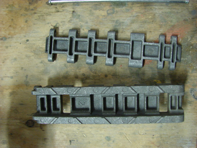
On the real King tiger the mud flap hinge was comprised out of three separate small blocks. To make the alteration I cut the one piece hinge into three small blocks. A hole was added to the center block hinge, and all six blocks had counter sinks drilled into them. The counter sink bolts will replace the cap screws that armortek recommends in their instructions. They all were then mounted to the tank with counter the sink bolts and weld beads. All that needs to be done to finish them up is to have some small putty work done to the counter sink bolts making them flush with the hinge.

Image

Image

Image

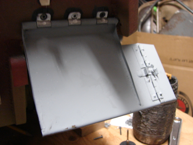
The mud flaps retain all of their functionality, and are very sturdy

Image

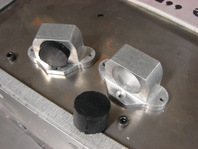
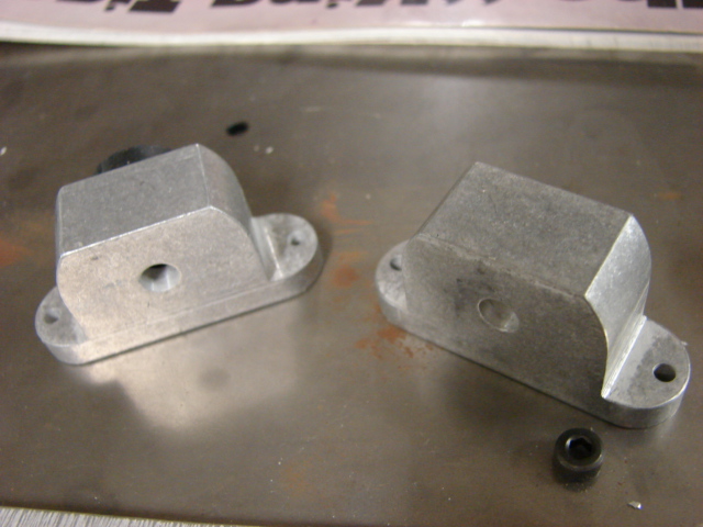
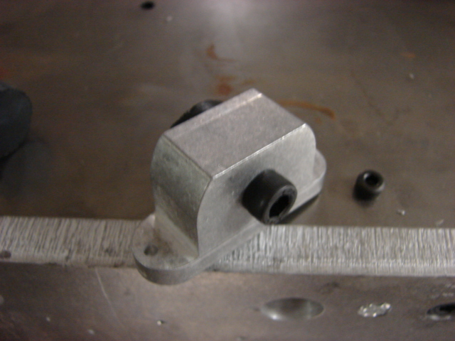
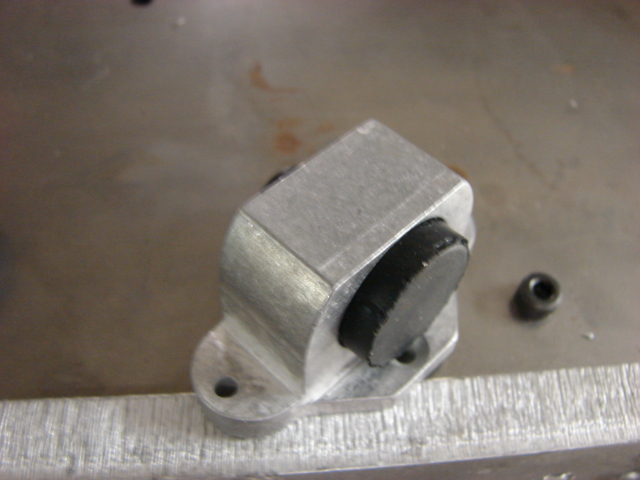
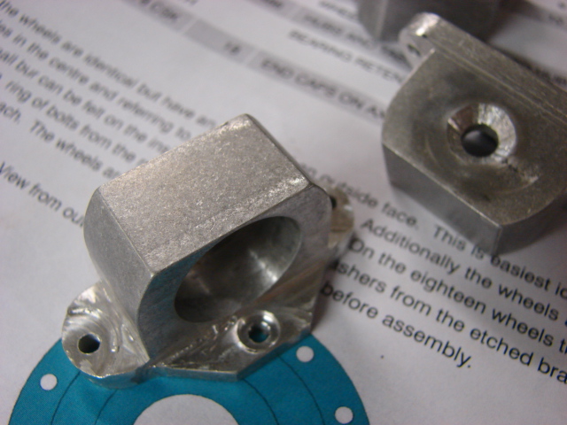
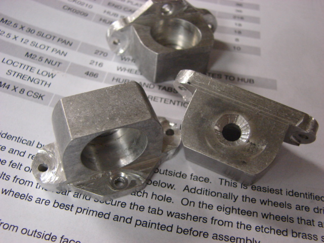
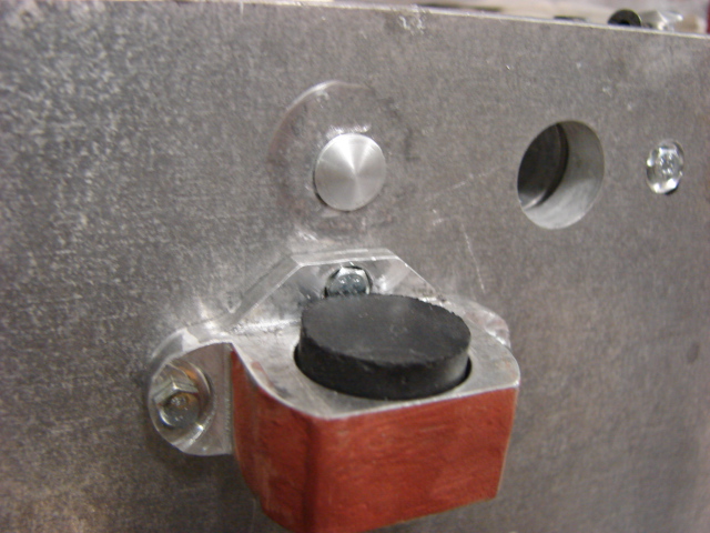
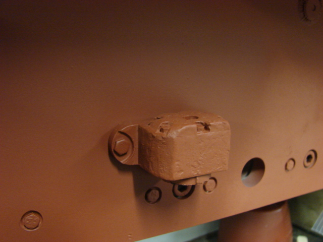
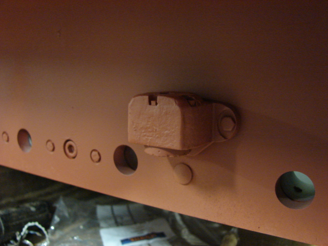
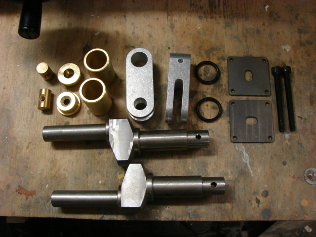
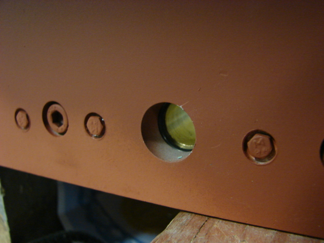
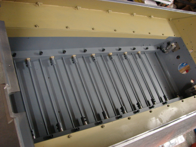
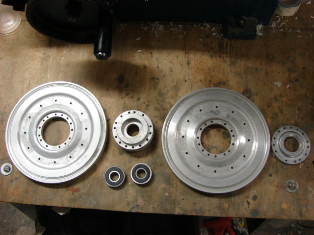
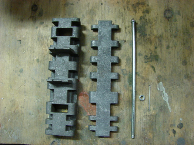
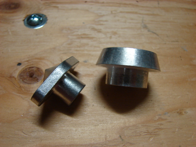
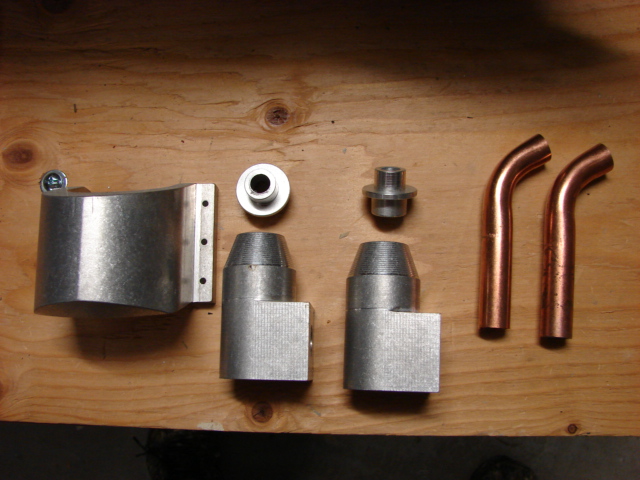
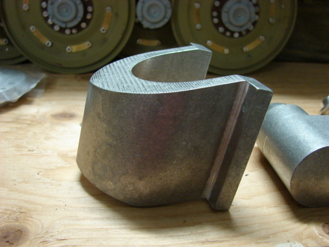
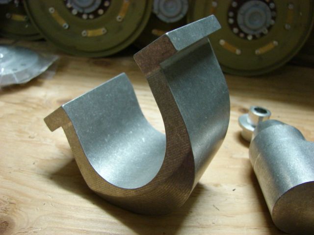
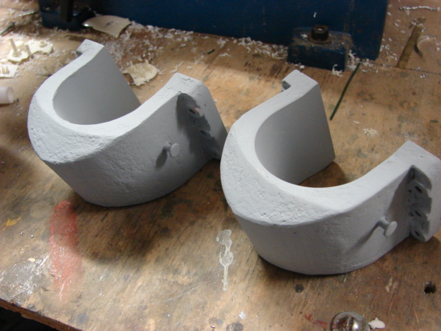
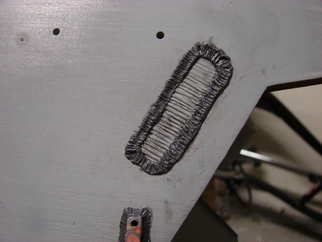
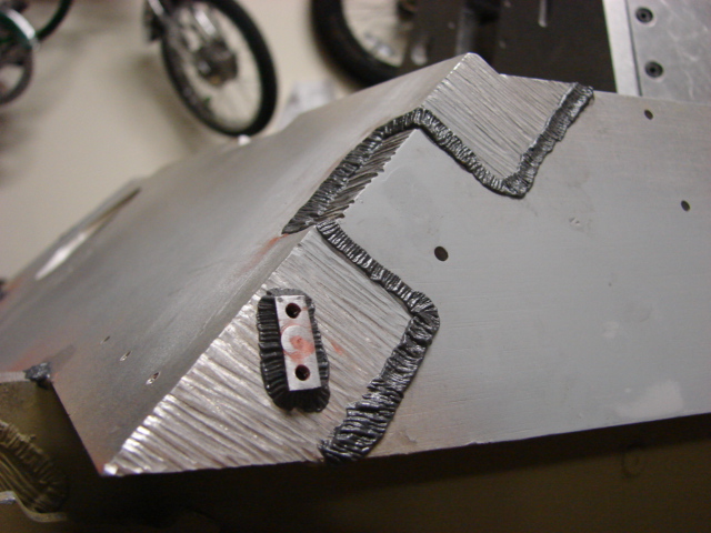
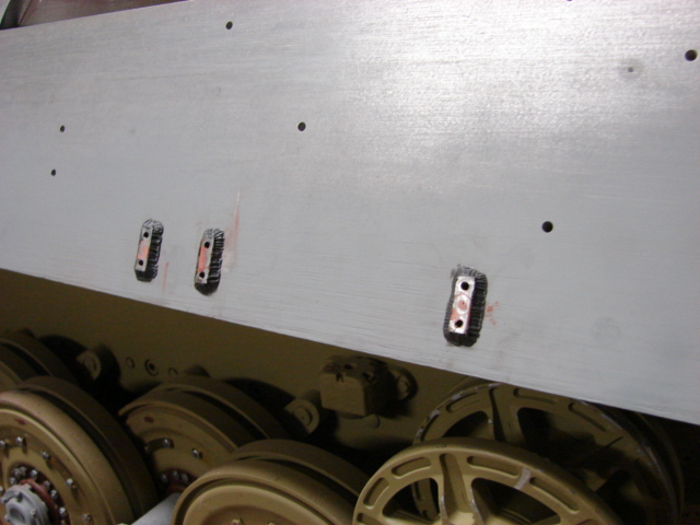
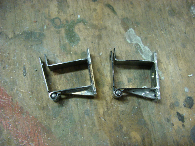
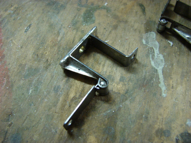
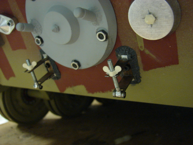
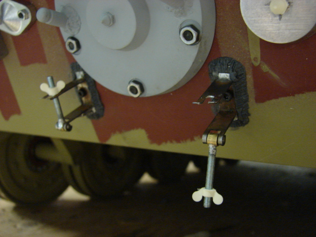
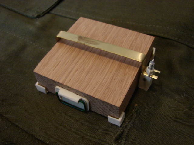
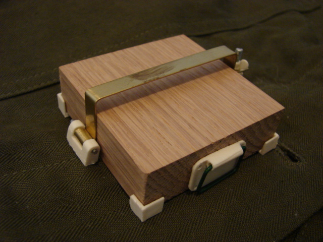
The tank's new jack block mounts were added. The Kit supplied jack block is comprised of a block of wood and a singe laser cut pre bent strip that gets bolted to the tank.

Image

Image

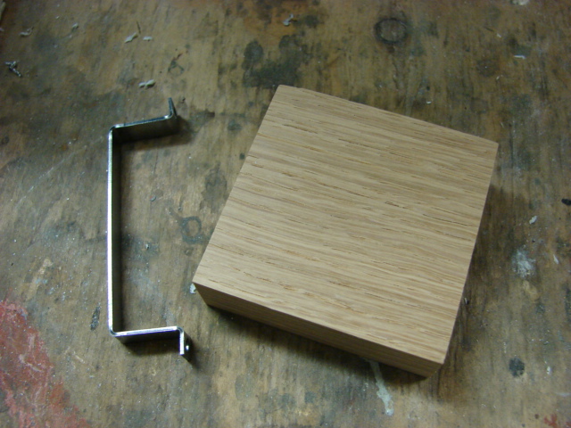
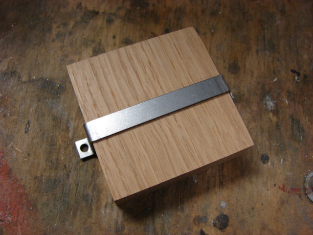
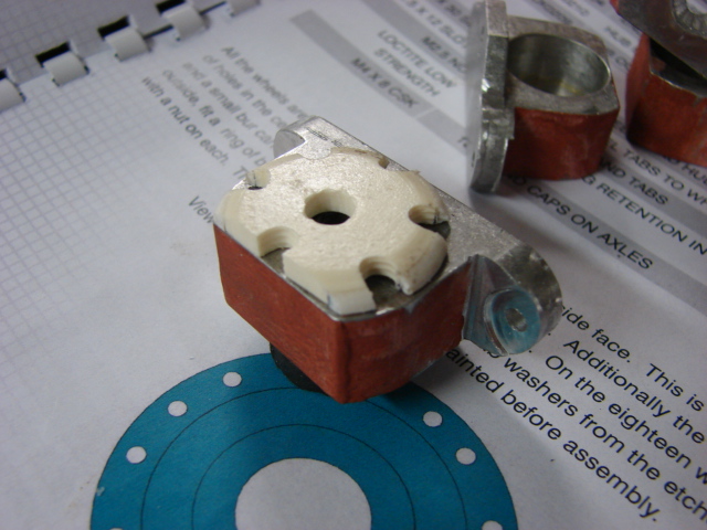
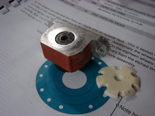
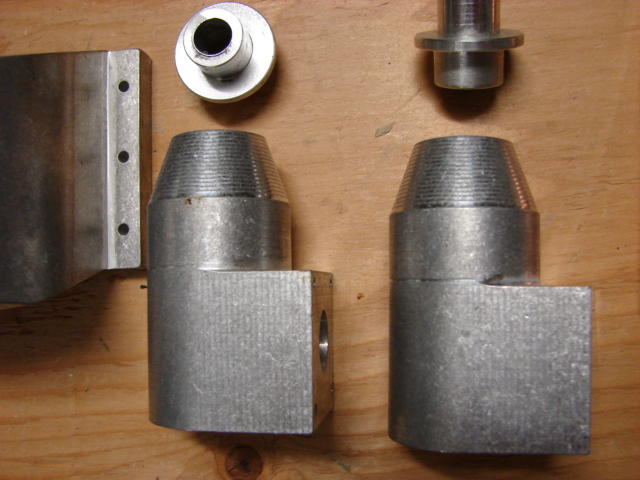
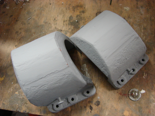
I decided to fabricate new jack block mounts that were full function and were more accurately detailed than the basic kit supplied version.

[img]htp://eastcoastarmory.com/german_parts/king_tiger_box/DSC00040.JPG[/img]

Image

Image

Image

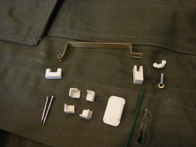
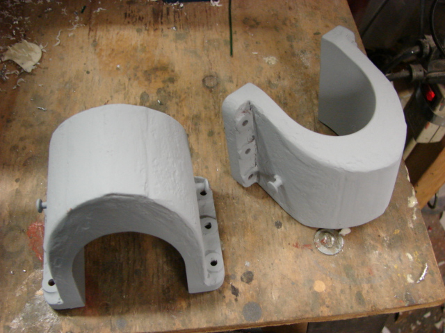
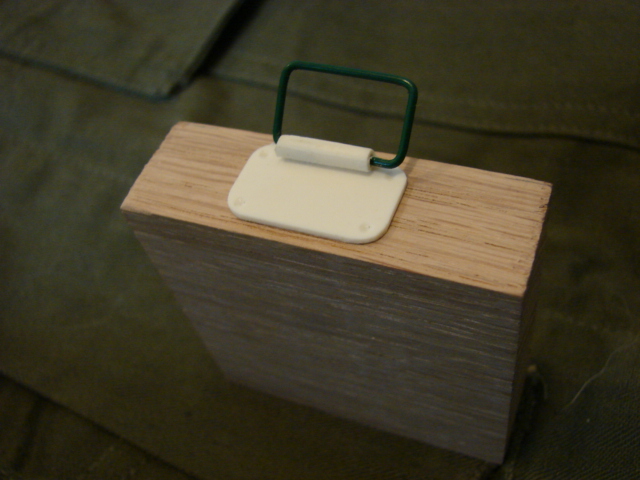
In addition to the new jack block mounts I also made the jack block carrying handle.

Image

Image

Image

Image

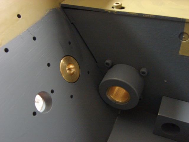
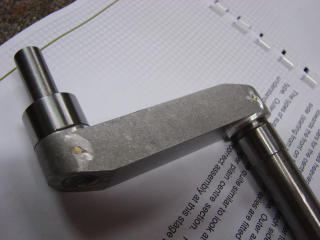
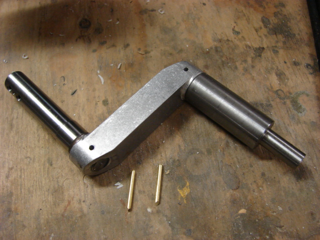
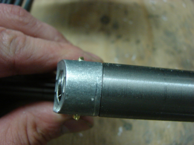
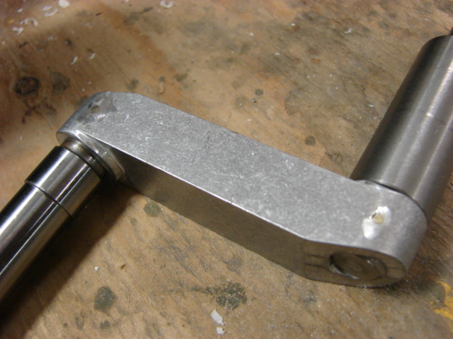
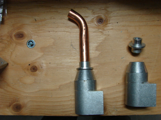
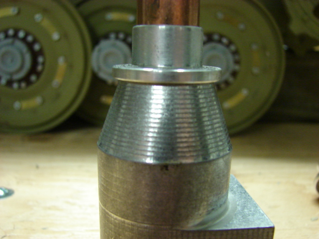
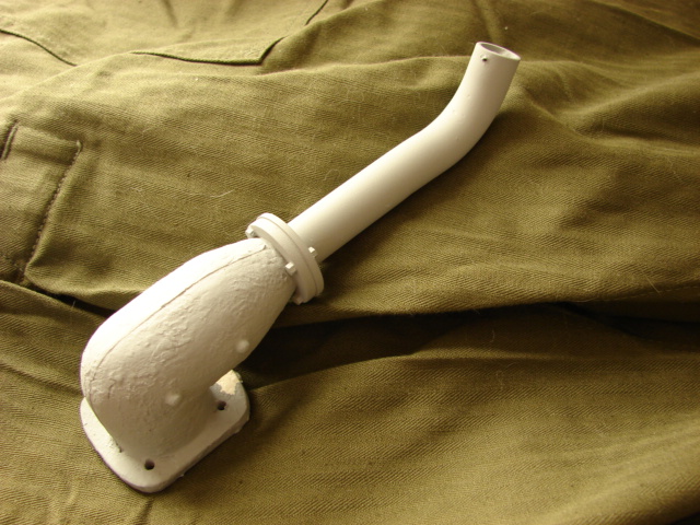
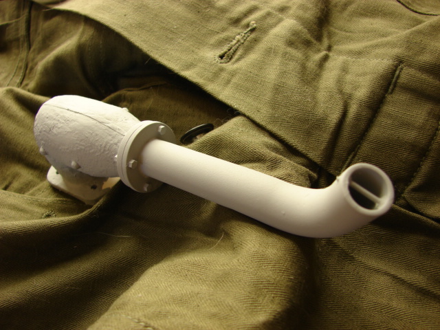
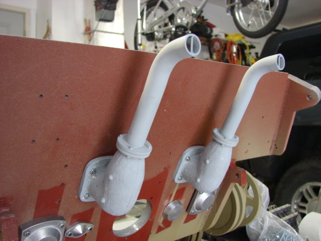
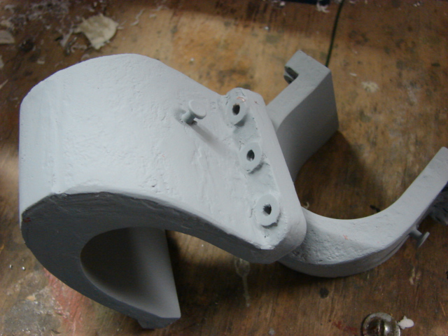
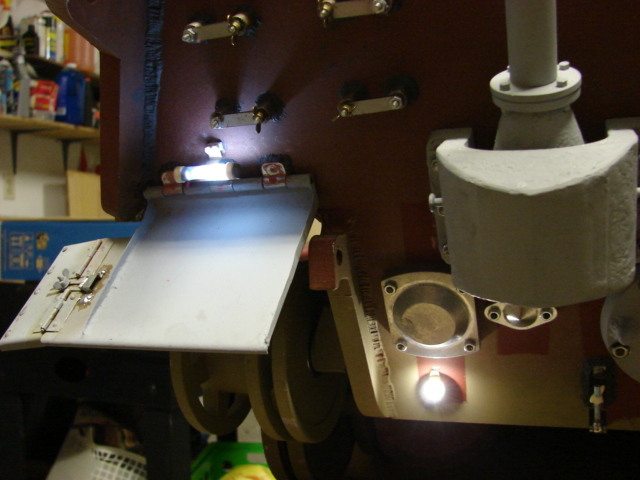
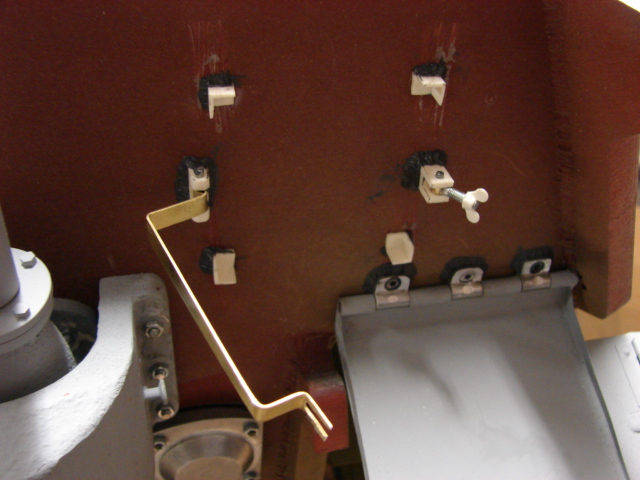
The pivoting crank handle guide was added to the tank’s right hand armored exhaust cover. The component does have a small length of chain and will be added once the tank is painted.

Image

Image

both the jack block detail upgrade and the pivoting crank handle set have been added to the product line.
http://eastcoastarmory.com/germanparts.htm

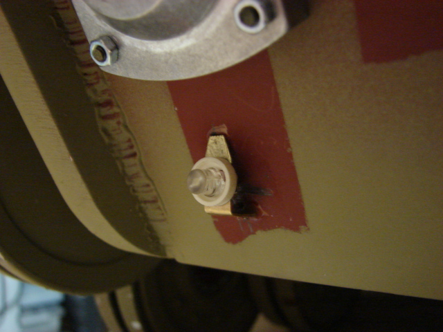
All that remains left to be fabricated is the tube tail light and the lower tail light. Once those parts have been completed the rear wall is 100% finished. More progress to follow!

John Grima
Posts: 250
Joined: Sun Jul 15, 2007 2:54 pm
Location: USA
Been liked: 48 times
Contact:

Post by John Grima »

I have made some more progress on the model.

Image

Image

The tank's final rear details have been scratch built and added. These would include the rear tail light and black out light.

Image

I made both of the rear lights function. for the lights I used two "White" LEDs. LEDs have many great advantages, but typically I don't like to use LED's for my model lights due to LEDs not having the amber glow that is found on incandescent light bulbs. But I'm using them for this application because the LEDs will be underneath colored lenses which will tint the color giving them a better richer color.

Image

To make the LED fit inside of the tail light mounts I needed to remove a section of the LED's top. Now the red lens will fit better over the LED once installed. This was carefully done on my lathe; this is also one advantage of LEDs over a light bulb.

Image

Image

Image

Image

A similar procedure was done to the blackout light, only the LED had its rimmed removed rather than its top shortened

Image

Image

Image

After finding more images of the rear mud flap details I revised the hinge lock and added a few more details. These would include riveting on the small side flap, and the flap stops.

Image

Image

Image

With the rear portion completed I then turned my attention to the tank's side panels. the body work for removing the bolt holes was completed leaving the sides perfectly smooth. After the body work and a shot of spot primer the torch cut lines were added to the front and rear armored plates. Simulated weld beads were then added.

Image

Image

On the front portion of the armored plate I only added the cut lines on the middle portion of the center puzzle square. This was done because I saw this type of cut on the Aberdeen Jadgtiger and I liked the look of the cut. This now completes the welds on the lower Hull. The next welds will be found on the top plate and the turret. The rest of the side detail (tool posts and tow cable mounts) will be added after the electronics have been added.

Image

Image

The side skirt mounting plates were also installed. The side skirt mount plates come with the kit and are made out of laser cut and pre drilled steel. They mount to the tank via a counter sunk Allen screw. These were mounted to the tank as is. After the plates were mounted I did a little putty work removing the sight of the counter sunk screw, and adding weld beads to all of the plates.

Image

Image

Image

I have also assembled both of the tank's tracks, These will be installed after the electronics have been added to test drive the model.

Image

All of the electronic components that I have order have arrived so I will now be focusing on the tank's functions now. Once complete I can proceed to the rest of the detailing. Much more to come :)

Post Reply